
In 2010, promoters and marketers agreed to construct a very visible power-generating project utilizing solar and wind in one of the busiest urban locations in the world – Times Square, New York. The power generated from this installation would provide lighting for the Ricoh billboard in the center of Times Square, with excess power stored in large batteries for periods of no sunlight and calm winds. At the inception of the project, photovoltaic panels had become fairly commonplace, but large vertical turbines utilizing wind resources to generate power had not been undertaken to this magnitude. From an environmental standpoint, the reduction of 52 short tons of carbon dioxide per year was very attractive. When CBI Consulting became involved, the scope of work was simply to confirm compliance of the 40-foot-long structure with the New York State Building Code.
The turbines had been manufactured in California and trucked across the country. From the manufacturer’s standpoint, the turbines were a product, not a structure requiring the services of a licensed engineer. The engineer for Ricoh, who had designed the supports for the turbine which projected from the Ricoh Building, sought assurance that the loads provided by the manufacturer were realistic and that the turbines, measuring 6 feet 7 inches in diameter by over 40 feet long, were of sufficient size to be classified as a structure according to the City of New York. What appeared on the surface to be a relatively simple task quickly turned into a complicated analysis, and involved the services of an erector and a mechanical engineer with knowledge about bearing function. Putting trailer truck-sized objects on the face of a building in Times Square was not going to be an easy task.
The calculations provided by the manufacturer were very basic, consisting of the weights of the turbines at the building connection points. When CBI began working on the project, one of the turbines was already in place on the side of the building and the manufacturer, having delivered the product, felt that its job was done. The engineering issues that had to be addressed in order to satisfy the local requirements included the following:
- Were the loads provided by the manufacturer accurate and sufficiently encompassing so that the brackets provided by the building engineer’s design were adequate?
- As a two-component manufactured product, but a one-component installation, were the loads appropriately distributed to the support points?
- Were the bearings that would allow the unit to spin adequate for the job?
- Would the turbine freewheel during high winds, or would it lockdown or modulate so as not to self-destruct?
- What was the appropriate load combination for design?
- How would the aerodynamic characteristics of the turbine change if ice were to form on the vanes?
- How did the effective wind surface change with ice build-up?
- How could the units be rigged for installation and removal so as to maintain appropriate alignment?
- Would it be possible to service/replace the generator and more wear-sensitive elements, such as the bearings, without having to remove the turbines from the building?
It became apparent that the engineering for manufacturing the product and the engineering for transporting and erecting the product were entirely different things. The realistic environmental loads (wind, ice, seismic) magnified the challenges even more. The manufacturer had success with a single 20-foot turbine, but needed two 20-foot turbines stacked in order to meet the allowable space on the building while generating the appropriate amount of power. Stacking the units made sense from a product standpoint, but created unknowns with respect to how the loads would be distributed to the building and within the combined product.
Rotation/wind speed test results from various turbine blade configurations.
With regard to wind issues, test reports for other models of the manufacturer’s product were not considered acceptable by the approving authorities (see chart). In order to verify the product design assumption that the turbine would stall and not self-destruct when the wind speed reached 80 miles an hour, the manufacturer performed a full-scale wind test of a 20-foot turbine at its site in California. Hess Engineering Inc. of Los Alamitos, CA observed and reported on this test. Having verified the manufacturer’s design assumptions with regard to high wind performance, it was still unknown how much load would need to be resisted by the connections to the building. Furthermore, what would be the wind effect on the components of a product consisting primarily of individual vertical panes and a central steel core? Product engineering calculations were absent in this regard.
Clearly, wind passes over the open turbine in a manner similar to the behavior of an airplane wing, but the percentage of wind that passes through was unknown. Treating the turbine as a two-dimensional solid sign placed a large penalty on both the product and the building supports. Through a process of rationalization, CBI determined that assuming a 76% solid sign would be an appropriate basis for generating the design loads that would be resisted by the connections to the building. The parties agreed that it was not necessary to combine a full code-level wind with the increased cross-section that might result from ice build-up. In fact, review of historical wind patterns in Times Square suggested that it would be almost impossible for this location to receive the code-prescribed, design-level wind load. In addition, the installation was planned for no more than a 10-year life.
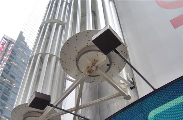
View from turbines from grade.
Proceeding forward, calculations revealed that reinforcement of supports for the turbine would be necessary. The product manufacturer disagreed with the approach, and did not agree to participate in the re-engineering of the product support components. Calculations confirmed the structural sufficiency of the vanes and the pipe core.
With loading issues resolved, the 5,300-pound turbines were removed by North Shore Sign from the Ricoh building and brought to North Shore’s shop on Long Island. The Ricoh project sponsors initially engaged North Shore solely to undertake the erection, but it turned out that their well-equipped metal fabrication shop would be needed for the structural retrofit. Once the turbines were at the shop and while they were being observed on the flatbed, it became apparent that even for the short period of time that they had been in place, components of the central bearing between the two 20-foot lengths had been sufficiently misaligned to cause scarring of certain components.
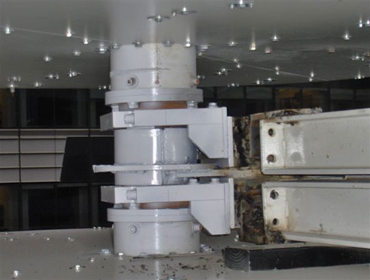
Mid-point collar connection between two 20-foot turbine sections.
That revelation highlighted the need to investigate the flexing movements of the turbines while being loaded for shipment at the manufacturer’s plant, flexing during cross-country transport, and erection from the horizontal to the vertical position in Times Square. The erector had received no guidance from the manufacturer as to the erection process, and simply used steps to which they were accustomed for normal billboard erection. In order to assess the movement that the units experienced, the team engaged the survey component of Nitsch Engineering of Boston to record flexing of the turbines during the erection process. That data would be used by CBI Consulting for a micro-evaluation of joinery elements.
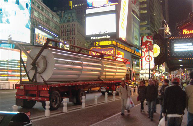
40-foot turbine arriving at Times Square.
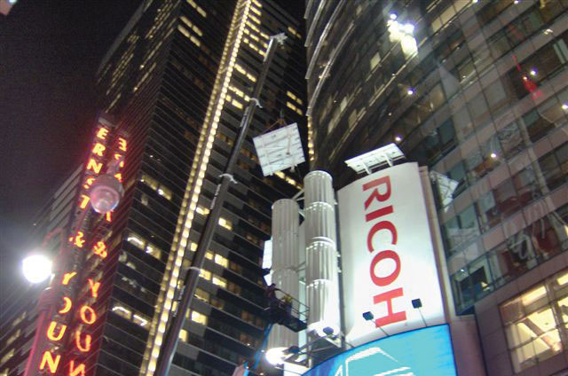
Solar panel installation with turbines in place.
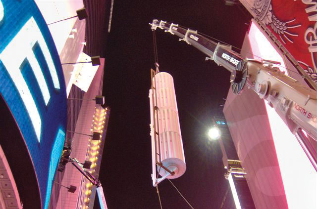
40-foot turbine suspended from the crane during installation process.
Engineering analysis revealed that using the current erection process would require the turbine unit to be disassembled and retrofitted with a more robust central connection. Alternatively, an external structural steel strong-back frame consisting of hollow structural sections (HSS) and extending the length of the two units – connected to the turbine at the top, bottom, and midpoint – would restrict the flexing so that the existing components would not be overstressed. The team chose the latter course of action as the best option. To provide further assurance, North Shore fabricated a structural metal containment collar to ensure that damage to the central connector, unseen during the erection process, would not progress to a point of instability.
During the process of sorting out structural issues, the manufacturer of the turbine developed a more efficient generator component. Furthermore, the new generator was also reported to be more robust and more easily swapped out for repairs should they become necessary. This would allow the turbine to remain in place for periodic servicing. Although the component itself was more costly, using it would eliminate the estimated cost to remove and erect the turbines (approximately $250,000 to cover working off-hours), Time Square traffic disruption, and the commitment of labor, materials, and equipment.
The main lesson learned from this experience is that product design, manufacturing, and engineering for a product of this complexity requires careful and thoughtful planning and coordination by all parties, well in advance of budgeting and manufacturing. The product engineer may be working with a completely different perspective than the structural engineer in the vertical construction industry.▪