
Each year, the American Society of Civil Engineers (ASCE) publishes a Report Card for America’s Infrastructure. Their rating system uses familiar academic grading (A through F) to report on the condition of America’s aging infrastructure. Last year, America’s infrastructure received a D+, indicating deteriorating infrastructure. Included in this report are waterfront structures, which are vitally important. According to ASCE, America has over 3,700 maratime terminals serving as commerce and transportation hubs.
Often, steel sheet pile walls are incorporated as part of cost-effective waterfront earth-retaining structures for these harbors. Many of these walls are subjected to salt-water exposure, tidal fluctuations, and a host of other environmental factors that accelerate corrosion. Even if the coatings are maintained and a cathodic protection system is employed, the corrosion near the waterline eventually necessitates expensive repairs and, often, replacement of the structure. Cellular sheet pile cofferdams are particularly difficult to repair because of the lack of redundancy in the tensioned cell walls. This article highlights a unique method to repair a cellular cofferdam using a reinforced concrete facing installed over the aging sheet piling.

Figure 1: Submarine pier aerial view. Courtesy of the U.S. Geological Survey.
Existing Structure Configuration
The submarine pier is located in the Hood Canal waterway in Washington State’s Puget Sound region. Considered a vital natural resource, Hood Canal provides vessel passage and is home to many aquatic species, some of which are fished for human consumption. The triangular shaped pier, accessible from land by two pile-supported trestles serves as a vessel docking-surface on two sides and a dry dock is integrated into the third side of the triangle (Figure 1). The concrete deck supports gantry cranes, mooring hardware, and a number of buildings. Most of the deck is supported by concrete piles, but portions are supported by a cofferdam that surrounds the dry dock structure. The cofferdam is formed by a series of circular interlocking steel sheet pile cells that form the outer perimeter of the dry dock structure. These sheet piles were vibrated or driven into the underlying seabed, and each cell was backfilled to form a cylindrical earth retaining structure. Additional sheet pile arcs connect each cell. In total, the dry dock uses 20, 75-foot diameter cells connected by 19 arcs in a U-shaped pattern that forms three sides of the dry dock structure. The fourth side is open to accept vessels and configured to accept a caisson (gate) that closes the dry dock off from the surrounding water. The internal cast-in-place concrete dry dock walls envelope portions of the cofferdam cells and arcs. However, at the outer perimeter, the sheet pile walls are fully exposed to the marine environment above and below the water line.
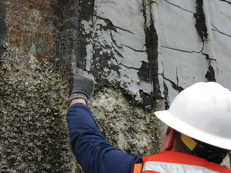
Figure 2: Existing failing cofferdam coating.
Field Observations
The first step in developing a comprehensive design strategy was to perform field investigations of the existing pile condition. From boat- and deck-based observations, the design team documented the condition of each exposed sheet pile face and noted special conditions that would need to be considered through the design process. The existing coatings were in a state of failure at most locations (Figure 2). The facility was equipped with an active cathodic protection system that consisted of anodes suspended from cantilevered beams extending over the cofferdam face. It is important to note that this type of cathodic protection system is fully effective only below the low water line, with reduced effectiveness in the tidal zone. The field observations also illuminated a number of construction constraints that would have otherwise been difficult to discern from a review of the design documents alone. The most surprising and important constraint was the restricted conditions under the deck. As shown in Figure 3, some existing concrete piles were less than 1 foot from the sheet pile face. The number and proximity of existing concrete piles would present a substantial access and construction challenge for under-pier work. Additionally, the design team observed a number of deck-based and water-based operations associated with the day-to-day function of the pier that would present a construction staging and sequencing challenge for the contractor.
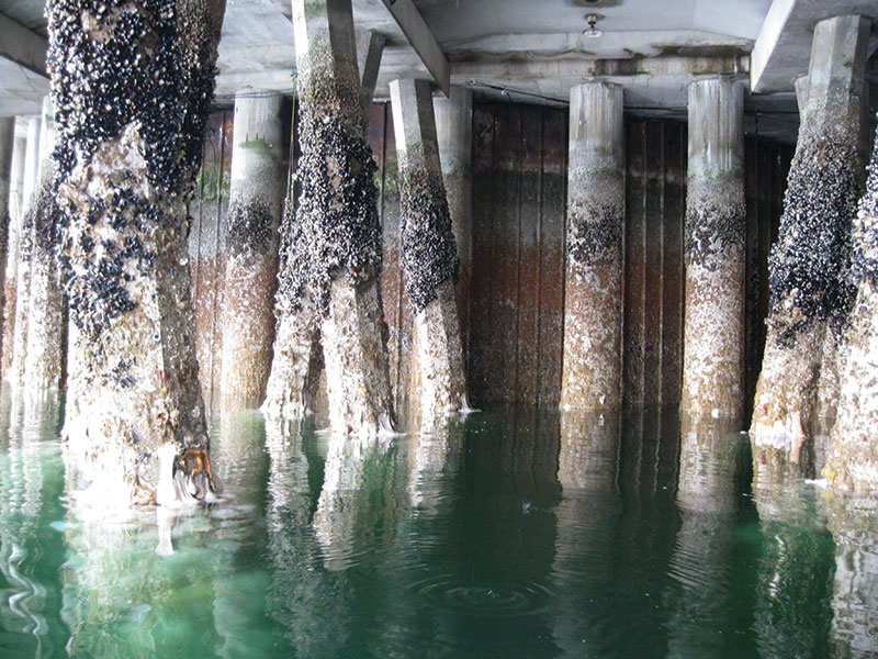
Figure 3: Existing concrete piers in close proximity to the cofferdam wall face.
Corrosion Mitigation Selection and Design Considerations
The owner considered a number of coating systems to mitigate further sheet pile corrosion: a high performance marine coating, thermal spray aluminum, copper-nickel cladding, and a concrete facing. Due to the considerable durability and low life-cycle cost, the owner chose a concrete facing extending from the top of the cofferdams to two-feet below Mean Lower Low Water as the preferred repair alternative. The owner called for a concrete service life of at least 50 years. Considering the cofferdam pile structure appeared to be performing well and did not exhibit excessive corrosion, the concrete facing would not be structural, but rather would provide an overlay to passivate and protect the steel cofferdam.
The concrete facing would present a number of different technical design challenges, but most of them would be related to one central issue: crack control. In this case, the design team had two related tools for controlling concrete cracking: rebar configuration and concrete specification.
Rebar Configuration
The design team considered that, during drying shrinkage, the formation of a crack requires a point or line of restraint. In this case, the vertical interlock joints between the sheet piles provided that restraint. Each interlock has two nested knuckles that protrude from the face of each sheet by about an inch. This protrusion is the line of restraint where an assumed crack might form. Table 4.1 of ACI 224R indicates a reasonable crack width for seawater spray is 0.006 inches, so this was adopted as the target crack width for the facing. Assuming the crack would form vertically, in-line with the knuckles, the primary reinforcement would be horizontal. Using minimum reinforcement, the resulting calculated crack width was 0.003 inches.
Concrete Specification
The basis of the concrete design was the owner’s specification for marine concrete with special considerations added for shrinkage control. Considering the non-structural nature of the facing, the concrete would not need to develop especially high compressive strength. This was advantageous because it presented the opportunity to lower the cement content in the mix, which would lower the water content, thereby minimizing shrinkage-induced cracks. This was accomplished by limiting the specified 90-day strength to a range of 3500 pounds per square inch (psi) to 4000 psi. Additionally, the mix incorporated a maximum water/cement ratio of 0.38 and a provision for rapid strength gain with age combined with a low shrinkage requirement. To assure maximum durability in this sea water environment, the concrete mix was proportioned to maximize its resistance to the penetration of chloride ions with a limit of less than or equal to 1000 coulombs at 56 days. The mix was also developed to limit the drying shrinkage to a maximum of 0.03% at 28 days.
Special additives were also required in the concrete. Much of the concrete casting was to be done underwater by divers in a bottom-up pumping operation. Due to the strict environmental requirements for working in the Hood Canal, anti-washout additives were required to prevent concrete paste leakage. Also, due to the long travel time and delays getting through the base, a set retarder was used.
Design for Constructability
The contractor would face a myriad of technical and operational challenges during construction of the facing. The following is a partial list of these challenges:
- Under-pier access was substantially restricted due to the close spacing of existing concrete piling.
- The curvature of the wall face would present a formwork challenge.
- The contractor needed to minimize interruption of pier operations. This would restrict construction laydown space and vehicle access. Additionally, the contractor would have to schedule activities around all pier operations.
- The construction crew and concrete deliveries would have to pass through checkpoints.
- The large distance between the jobsite and the nearest concrete batch plant would make the efficient delivery of concrete even more critical, as the mix is intended to have rapid strength gain as part of the shrinkage control strategy.
- The tidal fluctuation is as much as 11 feet, so the work schedule would have to consider tidal conditions.
- Due to the presence of protected aquatic species, in-water work was restricted to a 7-month period, called a “fish window”, starting in July.
The operational nature of these restrictions made mitigating them by design difficult. Some modest mitigating design strategies included provisions to make construction of the panels as flexible as possible, like simple rebar layout and coordinating the welded-headed-stud (WHS) spacing and rebar spacing to minimize the amount of additional rebar. Prior to construction, the designers and contractor also conducted a constructability meeting to review the design. This resulted in a number of adjustments:
- Welded headed studs were pre-fabricated on steel bars, which were then fillet welded to the sheet pile face (Figure 4). Considering the large number of WHS’s on project, this would save substantial time by minimizing layout and welding time in the field, some of which had to be done under water by divers.
- To more easily accommodate the in-water construction restriction, the contractor implemented a horizontal cold joint, which broke the facing into “uppers” and “lowers.” This would allow the contractor to pour the “lowers” when in-water construction was allowed and could continue construction above-water on the “uppers” between the fish windows. Figure 5 shows a completed “upper” in an under-pier condition. The only changes required to accommodate this configuration were a minor modification to the welded headed stud layout at the cold joint and the implementation of epoxy-coated vertical bars, at the joint locations only.
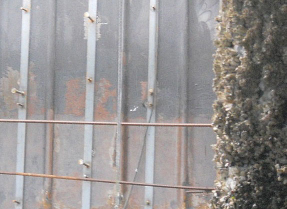
Figure 4: Pre-fabricated welded headed stud rails. Courtesy of Seaward Marine.
Test program and Completion
Since the construction of the facing panels would be so difficult, contract documents included provisions for a test wall segment. This would mitigate risk in two ways. One, it would give the contractor the opportunity to refine the construction process while including provisions in the budget to re-construct the wall if necessary. Two, it would give the owner and designers the opportunity to inspect the wall and adjust the design if necessary. The test wall segment would be constructed with the intent to remain as the first section of the wall if all tests and inspections were acceptable. The wall segment was located to capture a representative collection of all the different existing conditions, including one cell, one arc, the cell-arc joint, and under-pier work. Cores were taken of the test wall segment to measure specific gravity, chloride ion penetration resistance, voids, and compressive strength. Additionally, it was an opportunity to evaluate the cracking at specific concrete ages. Figure 6 shows a typical cell and arc with completed “uppers” and “lowers.” The test wall was a success and remained as a permanent part of the facing. After the test wall was approved by the owner, the contractor constructed the project faster than expected, allowing it to be finished ahead of schedule. During the last on-site observation, the facing appeared to be performing very well and very few cracks have formed. As you might expect, the owner is very pleased with this outcome.
Conclusion
This project demonstrated the successful use of what amounts to a thick coat of “paint” made of high-tech concrete to repair an aging sheet pile cofferdam located at a very challenging site. While more expensive to install than other coatings, this solution is estimated to offer the greatest long-term durability and lowest lifecycle cost. Additionally, this solution was installed with relatively little impact to the facility operations.
With America’s infrastructure, including over 300 harbors, in a deteriorating state (remember that D+?), having cost-effective and flexible strategies to mitigate corrosion while minimizing day-to-day facility operations is imperative. If you find yourself faced with a replace or repair scenario on a quay wall or cofferdam, consider using a concrete facing to extend the structure’s life. After going through this project, I’d give the strategy an A.▪
Project Team
Owner: US Navy
Structural Engineers: KPFF Consulting Engineers, Seattle, WA
Cathodic Protection Engineers: Norton Corrosion, Woodinville, WA
General Contractor: Seaward Marine, Chesapeake, VA