
Founded in 1990, Church of the Resurrection is the largest United Methodist Church in the U.S. In 2012, HGA Architects and Engineers (HGA) joined Church of the Resurrection’s mission to create a permanent sanctuary at their 76 acre Leawood, Kansas, campus. Design for the new 140,000 square foot main sanctuary and support space began in November 2012 and spanned a two-year period until construction documents were issued in November of 2014. McCown Gordon Construction broke ground in March of 2015 and completed the construction over a period of two years, ending March of 2017.
Projects with demanding design challenges often provide new opportunities for innovation and result in very rewarding engineering solutions. The Church’s desire for an intimate 3,500-seat, lofty, naturally lit sanctuary provided many such challenges. HGA’s architectural vision resulted in canted exterior and interior walls hiding columns and lateral cross-bracing, non-orthogonal beam framing with several convergent connections, and a column-free sanctuary volume with balcony seating.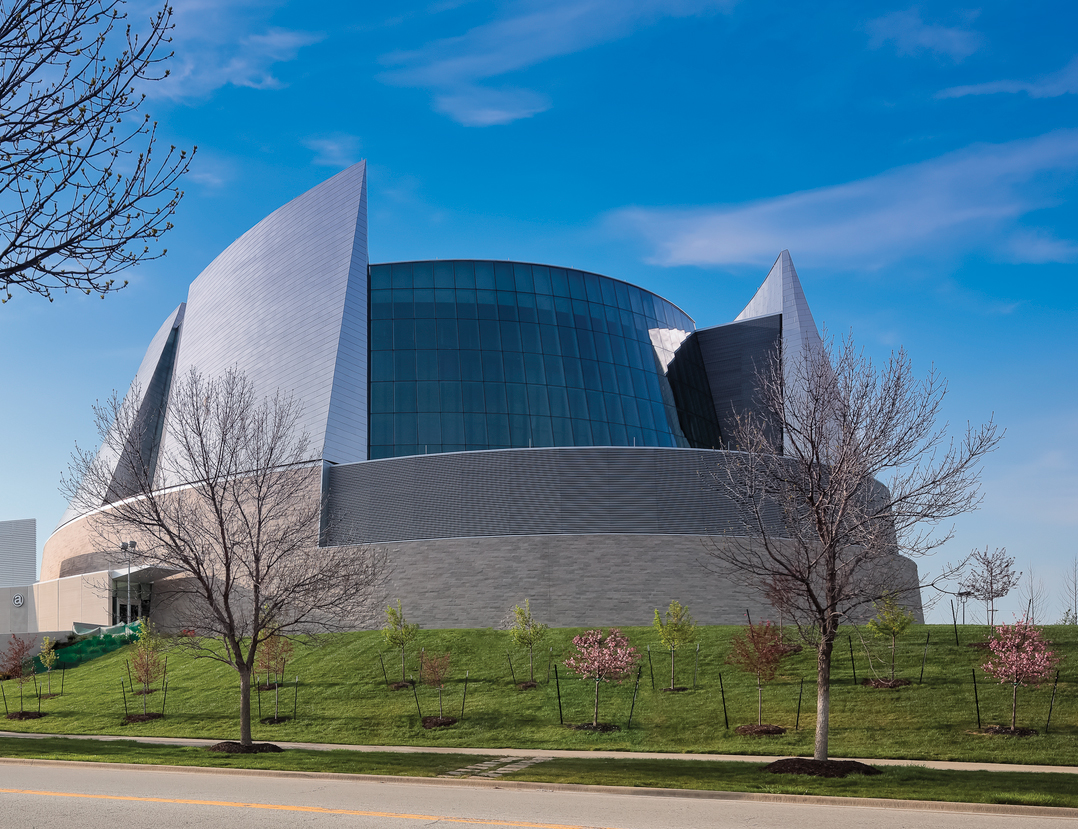
Ellipse
The shape of the sanctuary was inspired by the Church’s request for a distance no farther than 100 feet from pastor to individual parishioner, resulting in an ellipse that cradles the chancel area. This shape set the stage for the building’s complex geometric layout. It became apparent early on that existing software platforms would struggle with the demands of a non-rectilinear and non-circular curved grid system. HGA’s design team decided to implement the use of four curves to approximate each ellipse. In addition to the main sanctuary base being an ellipse, the architectural vision for the sanctuary shaped the sloping exterior wall and structural system, creating multiple shrinking ellipses as the building rises. Topping the building off are seven stainless-steel sails inspired by the seven days of the Holy Week.
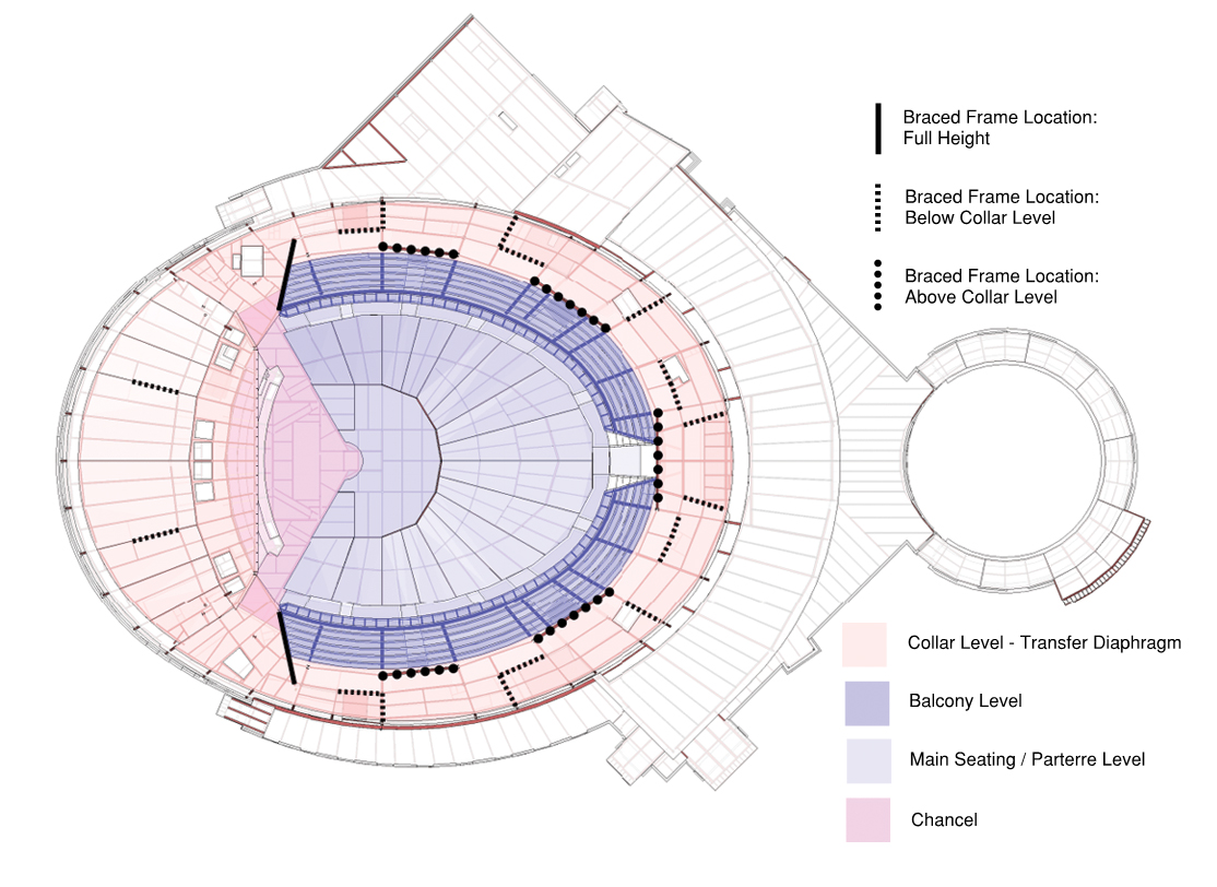
Figure 1. Horizontal offset plan.
The desire to achieve a canted exterior wall, high ceilings, and long-span open sanctuary volume lent itself to the economy of steel construction. Steel braced frames along the elliptical grids were offset at the collar level, creating a horizontal out-of-plane offset discontinuity to accommodate the sloped sail cladding structure and transfer the lateral wind load (Figure 1). The structural team used linear segmented beam runs between columns in lieu of radiused beams along slab edges to keep steel fabrication costs down. The framing layout of segments built within a curved form created a condition where orthogonal connections were essentially non-existent and generated several complicated connection points with multiple beams converging on a single point. Without the orthogonal relationship between purlins and girders, nor between girders and columns, the use of standard 90-degree single angle and double angle connections became impossible. Consequently, new project typical connections were generated in partnership with the steel fabricator, KC Structural Steel, while remaining mindful of time, money, and erection costs. When the angle was tighter than 45 degrees, single angle bolted connections with the toe of the outstanding angle welded to the girder web were used (Figure 2a).
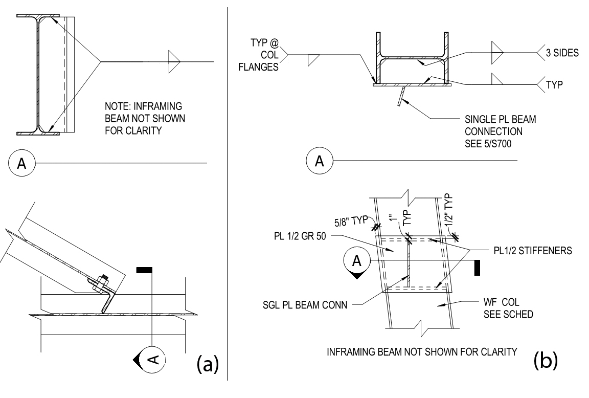
Figure 2. Typical connections.
When girders framing into column webs were required to have extensive and varying top and bottom flange cuts on both sides of the beam web, a column flange cover plate with skewed single plate bolted connection was created (Figure 2b).
A colonnade wraps the sanctuary and opens into a 15,000-square-foot gathering space with 20-foot high ceilings and a continuous skylight dividing the adjacent ancillary structure from the main building structure. Wide flange beams punch through at discrete points from canted column connections at the perimeter of the sanctuary, splaying out in rays. The lateral analysis for the lower ancillary space was performed separately from the main sanctuary form by effectively unfolding the diaphragm and transferring the lateral load back to the building’s lateral force resisting system in the sanctuary via canted column bending (Figure 3). A combination of hand calculations, modeling in RISA 3D, and modeling in SCIA Engineer was used to accomplish the combined lateral analysis for the sanctuary space and gathering space.
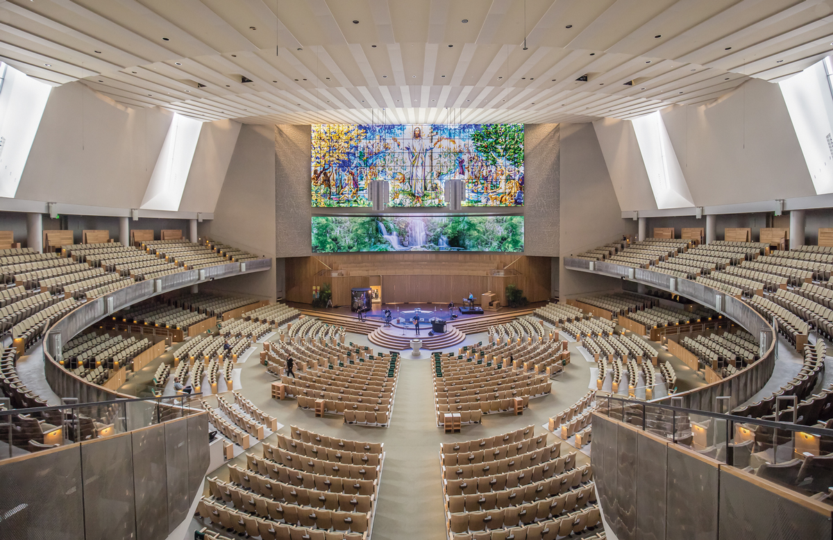
Figure 3. Sanctuary space.
Long Span Roof Trusses
Meeting the client’s desire for a lofty, open sanctuary space meant incorporating long-span roof trusses. Sloped wide-flange beams at the roof deliver loads to the trusses. Due to the sanctuary’s elliptical geometry, all six roof trusses differ, resulting in six distinct truss designs ranging from 110 feet long and 8 feet deep to 181 feet long and 13 feet deep, with truss chords ranging from W14x61 to W14x109. The panel points over most of the truss length are spaced at 10 feet to align with the wide flange beams, while the outermost panels made up the difference between the standard 10-foot module and the spacing between the support columns. The truss-bottom chords bear on the support columns, and the outermost “vertical” truss web members are sloped to facilitate the cladding structure for the “sails” that reach skyward on the building’s exterior.
The structural engineers worked closely with the architects early in the design to identify truss geometry constraints such as panel width (to facilitate catwalks and mechanical systems) and truss depth based on proposed ceiling structures. The structural team parameterized the truss depth in SCIA Engineer to quickly run through design iterations, searching for the most efficient design while meeting the constraints.
Balcony Trusses
The project required a thin, front profile balcony with a shallow depth truss to accommodate high ceilings and unobstructed sightlines from the back row of the tiered parterre seating. This ensured an open yet intimate and reverent experience.
The 1,300-seat balcony is supported by cantilever trusses, with chords as heavy as W14x193 which extend out from pairs of columns spaced on radial grids around most of the elliptical base. The columns, up to W14x211, make up the backspan to the cantilevered balcony and resist the moment via a couple into the foundation system. Vibration serviceability demands controlled the truss design over the required strength.
The structural team developed analytical modeling techniques and created project-specific vibration performance criteria using several documents pertaining to vibrations, including: AISC Design Guide 11: Floor Vibrations Due to Human Activity, A Design Guide for Footfall Induced Vibration of Structures (United Kingdom publication, The Concrete Centre), and International Standard ISO 10137 Basis for design of structures – Serviceability of buildings and walkways against vibrations. A separate analysis model was built, including all of the members contributing to the mass and stiffness of the system down to the foundation, to determine the structure’s behavior subject to excitation. Based on the anticipated use of the space, the structural team set a minimum fundamental frequency to meet a peak acceleration limit equal to five percent of gravity with a dynamic loading function criterion for a “lively concert” as defined in AISC Design Guide 11.
Wind in the Sails
The stainless steel “sails” soaring above the stone clad base of the church and the non-rectilinear shape of the church are not described in building code provisions for the application of lateral loads to a building structure. The structural team had to develop a rational approach to apply prescriptive code lateral loads to the sail structure.
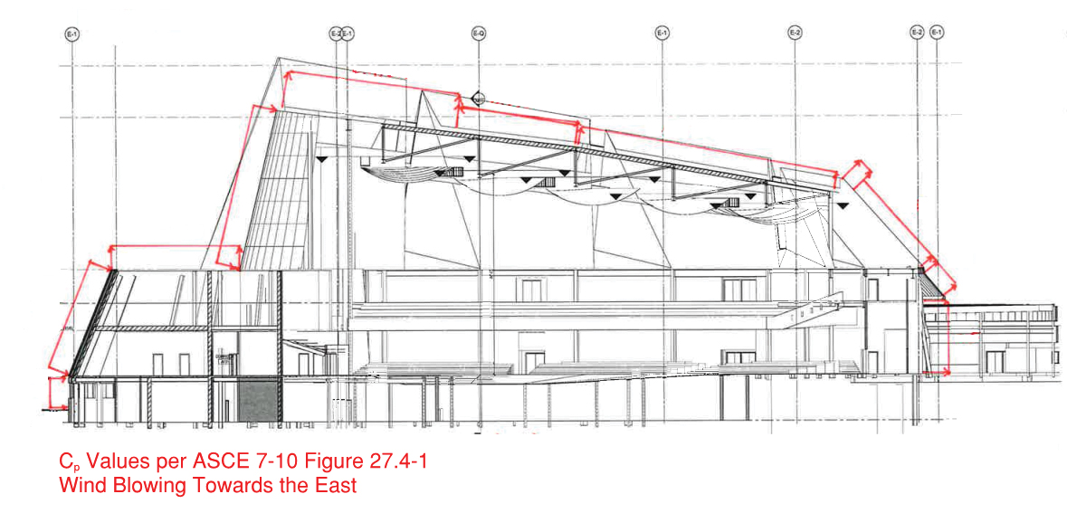
Figure 4. Sail wind loading.
After several discussions among members of the structural team, and a few brainstorming sessions with structural department members from HGA’s other offices, the team decided to apply wind loading perpendicular to a plane that represents the curving sail cladding marching around the building at 30-degree sectors to cover wind loading from any direction. Portions of the building were identified as windward, leeward, or sidewall, depending on which sector the wind was assumed to be blowing (Figures 4 and 5). The structural team used the architect’s Rhino sail geometry model to define planes representing main portions of the sails. Design wind pressures per ASCE 7-10, peaking at 46 psf, were assumed to act perpendicular to these planes. The design wind pressures were broken down into X, Y, and Z components, using vectors normal to the assumed plane and imported as applied loading in the analysis model.
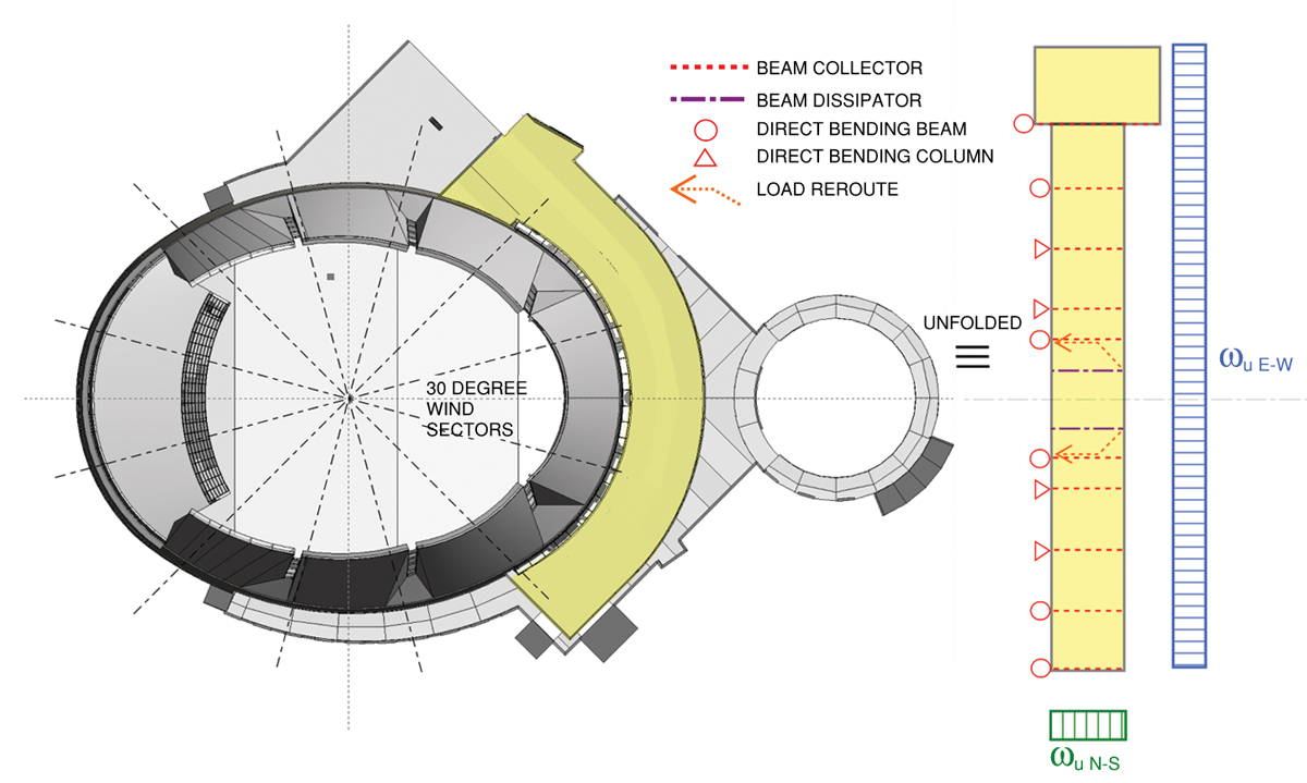
Figure 5. Wind load sectors.
Art Glass
One component of the sanctuary project gave structural engineers an opportunity to provide expertise for an extraordinary element. Church of the Resurrection is home to the largest stained-glass window installation in the world. The 93-foot by 37-foot stained-glass window provides the reverent backdrop during services and acts as a beacon to the community. Each of the 161 individual stained-glass panels is supported by vertical and horizontal aluminum mullions. The aluminum mullions tie back to architecturally exposed structural steel HSS 8×2 tubes. The HSS members provide the lateral support for the 5 psf internal wind pressure and delicately control the serviceability limitations of the art glass installation. The structural engineers, glass artisans, and the construction team carefully coordinated design requirements to develop appropriate deflection limits, installation details, and erection tolerances. Each HSS member spans 46 feet from collar level to the underside of the roof deck above. The allowable maximum wind load differential deflection experienced across the 5-foot 2-inch height of one individual glass panel was L/175.
Conclusion
The structural team was able to manipulate the building structure and design software to work within the confines of the complex building geometry. The desire for an open and lofty sanctuary warranted an economizing design of long-span roof trusses and occupant comfort-driven design for shallow depth cantilever balcony trusses. The non-orthogonal building shape necessitated a practical lateral load application and analysis process for design wind loads. The team’s mindful placement of braced frames within the architectural form created a discontinuous lateral load path to reconcile. HGA structural engineers elevated their thinking and developed innovative solutions to meet the challenge of making the sacred vision for this building a reality. This was accomplished by creatively analyzing irregular diaphragms, accommodating slanted columns, and developing appropriate structural steel backup design criteria for the world’s largest stained glass window installation. The Church of the Resurrection is a recent recipient of the ACEC 2018 Engineering Excellence Minnesota Grand Award and National Recognition Award.▪