
Rising along the Chicago River, Vista Tower poses a never-before-seen structural challenge: how to design a 1,200-foot-tall building constrained by a plan width of 80 feet and vertical support elements that offset at every level. After years of planning and design, construction is underway on Chicago’s third tallest tower, using an aggressively unique building geometry and lateral bracing system arrangement. The iconic architectural vision of Studio Gang’s Jeanne Gang, in conjunction with Magnusson Klemencic Associates’ (MKA) innovative structural solutions, has been realized and is scheduled to be completed in 2020.
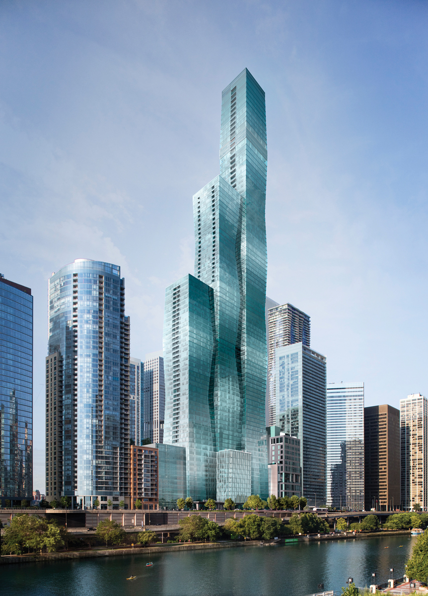
Building rendering across Chicago River. Courtesy of Magellan Development Group.
Centerpiece of an Urban Renewal
The Lakeshore East neighborhood on the Chicago waterfront has redesigned itself during 200 years of re-envisioning lakefront priorities. Residing just south of the Chicago River, the shoreline was originally used for wharves and docks as the city built itself at the mouth of the river in the early 1800s. When the city became a pivotal inland shipping and transportation hub, the area was transformed into the rail yard for the Illinois Central Railroad in the 1850s. Later, the rail yard was transferred off the waterfront, and this 28-acre property was reformed into a municipal golf course, hidden between 40-foot-tall viaducts.
During the urban renewal of the late 1900s, this land was master-planned for residential, hotel, and park use, reconnecting the dynamic commercial core of Chicago’s Loop to its vibrant waterfront and extending the walkable, publicly-activated Millennium Park north to the Chicago River. Vista Tower is one of the final parcels of the Lakeshore East development to be built and is situated and sized to be the centerpiece of this urban residential village.
Stacked-Alternating Frustums
In its essence, Vista Tower is a combination of many parts. The building will include three uses; hotel, apartments, and condominiums, vertically stacked. The primary form of the building is three connected towers of 100, 75, and 50 stories, offset in plan to create distinct and unique site-lines for the buildings’ occupants.
Composing these towers are unique, geometric elements: 13-story frustum blocks stacked and alternated in both plan and elevation. A frustum is defined as a truncated cone or pyramid. The form selected for Vista Tower’s building blocks is cut from a pyramidal shape, resulting in a square-sided volume tapering from 90 feet at its widest to 80 feet at its narrowest. The 100-story section of the building uses seven frustums flipped end-for-end with each instance so that the end form is a very narrow, vertically undulating exterior. The lowest frustum tapers for more than 13 stories and lands on a 5-story vertical base, bringing the total story count to 100.
The 75-story section of the building includes five frustums, again alternated end-for-end as they stack, but with the inverse orientation from the frustums in the adjacent 100-story mass. This has the effect that any given floor is smaller than the floor below it in some areas and larger than the floor below it in other areas. To complete the pattern, the 50-story section of the building follows suit, again stacking a smaller number of frustums also with inverse orientation from the adjacent mass. The resulting façade has eight corners at shifting locations on every level, allowing for no consistent vertical or horizontal lines.
Supporting 100 unique floor plans with a rational column arrangement proved to be fundamental in shaping the buildings’ structural DNA. Locating straight columns justified with the exterior of the narrowest frustum levels would place them five feet inside the glazed corners on the widest floors of the frustum. This would have created an untenable condition in which the most desirable part of the units, the corners, were compromised in both floor plan use and view of the surrounding city. An alternate solution was explored where column locations follow the tapering building exterior, shifting at every floor and remaining tight to the façade. With column axial loads as great as 15,000 kips at the base, the implication of shifting columns presented real challenges to global stability and building balance.
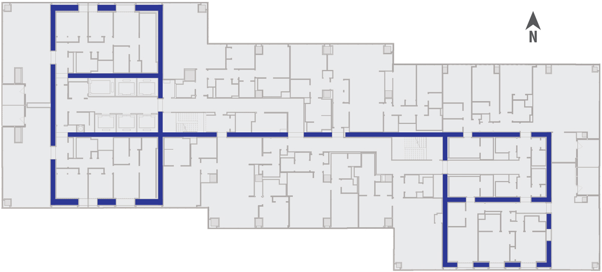
Shear wall layout shown in plan.
This geometry ultimately proved viable, incorporating column horizontal offsets of approximately 5 inches at every level. Since the stepping of columns is consistent around each frustum, the effect to the overall system is negligible. The exception is, at the top and bottom of each frustum, where the direction of column stepping reverses. This required a significant lateral restoring force at that elevation, supplied by the floor slab.
At frustum wide points, the induced force is an outward pull on the slab, felt in two directions at corner columns. This tension is handled with mild reinforcement, located mid-height in the slab and carried entirely across the floor plan to an “equal and opposite” column. At frustum narrow points, the equilibrating force compresses the slab. This results in a P-delta condition for the slab, causing the slab’s initial gravity moments and deflections to be amplified by the induced axial forces. The developer’s goal of maximizing clear height and having clean slab soffits meant this P-delta problem needed to be solved without adding beams or other thickened elements that would conventionally carry compression. Analyzing these slabs as compression elements, while considering the gravity deflections and slab post-tensioning as initial conditions, revealed an arrangement of supplemental reinforcement necessary to keep these elements stable.
Another critical design decision, stemming from having 100 unique floor plans, was determining how much granularity to apply to the detailing of the slab reinforcement (rebar, post-tensioning tendons, and studrails). The most optimized design suggested every level entailed a unique design, perfectly matched to the spans. However, the resulting volume of details would create a massive burden on the contractor to manage shop drawings, fabrication, storage, placement, and special inspection unique to each level.
The other extreme would be to apply the design for the worst-case slab, the widest level and longest spans, to all levels in that frustum. This solution would be both overly wasteful of material and would create an overload of load-balancing from the post-tensioning tendons when applied to the short-span levels.
The chosen design approach hit the mid-point between these competing interests of optimization and constructability. Each 13-story block of slabs is broken into three designs, considering small, medium, and large span levels separately. Other than the 20 levels of hotel, parking, and mechanical use, the remaining 80 levels are covered by just 18 unique slab designs.
Wind Resistance and Optimization
Buildings of 500 feet and shorter are often braced with wind-load resisting framing that neatly disappears into the floor plan. Typically, a concrete wall assembly, arranged to surround the central core of elevators, stairs, and shafts, braces the tower leaving the remainder of the floor plan open and free for efficient room layouts with unobstructed views at the perimeter. For taller towers, the concrete core alone is too narrow to provide the requisite strength and stiffness. A ratio of building height to lateral system stance of 12:1 is aggressive. For Vista Tower, the ratio of building height to core width is approximately 40:1, which required widening the stance of the lateral system beyond just the core.
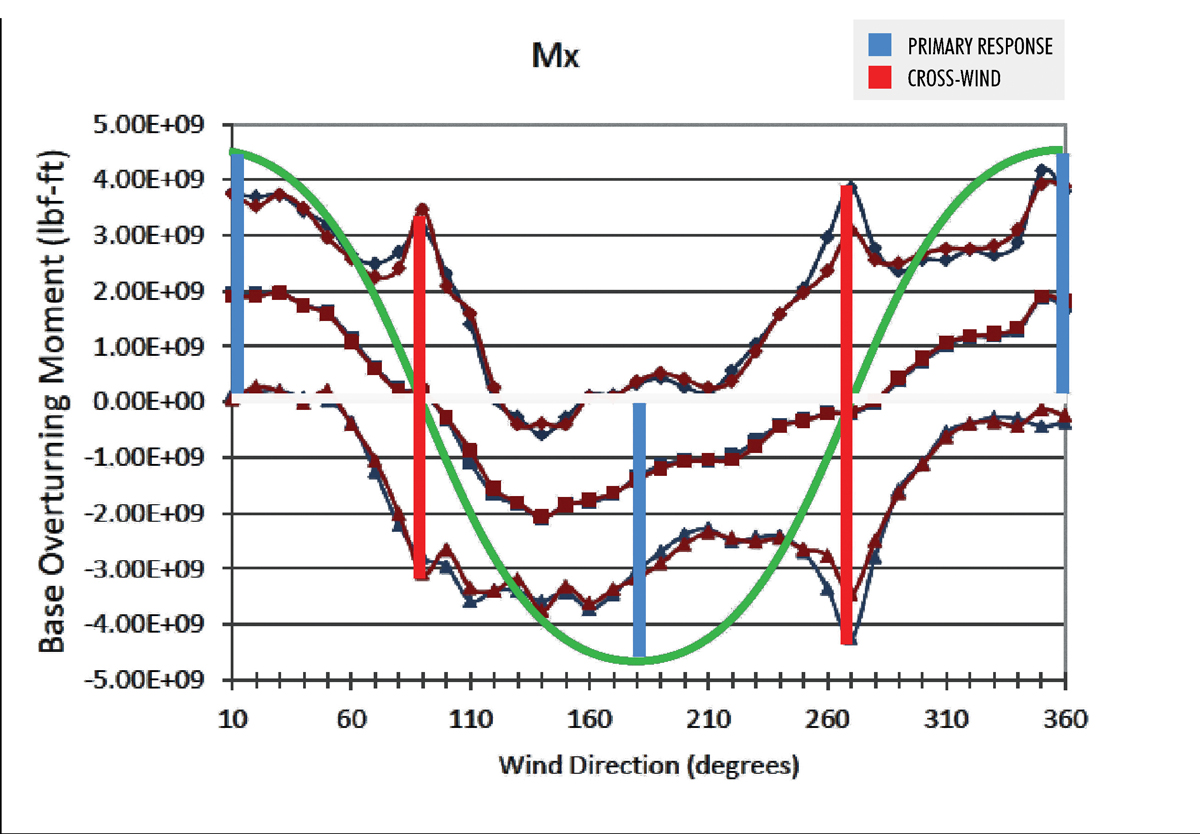
Base overturning moment from variable wind direction.
In the east-west direction of the tower, a convenient geometry was provided by the presence of two primary circulation cores, one in the 100-story portion and one in the 50-story portion. By slightly adjusting the offset of tower masses, the cores were aligned in plan and connected with a concrete wall running along the length of the corridor between them, creating a spine for the building plan. The result is a coupled dual-core shear wall assembly resisting wind forces from the predominant direction, the West.
Through detailed wind tunnel studies, it was determined that the prevailing winds caused a strong cross-wind response. This is a condition when the wind blowing on a building in one direction causes forces and sway in the perpendicular direction. Cross-wind response is generally prevalent at higher wind speeds when vortices forming on the backside of building discontinuities release and reform with cyclic timing. When the frequency of release starts to match the buildings’ natural frequency of sway, resonance begins, and cross-directional forces amplify. These effects were revealed and quantified by wind tunnel testing in Guelph, Canada, by Rowan, Williams, Davies and Irwin (RWDI). RWDI’s testing revealed that cross-directional loads in the north-south direction were 16 percent greater from westerly winds than from winds actually blowing in the north-south direction!
Resisting these north-south wind loads proved to be the most significant structural challenge of the project and the most impactful to the hotel and residential unit layouts. Creating a north-south lateral system with a stance close to 12:1 required activating the entire building width. One common solution to this problem is to use a series of outriggers extending from the core to exterior columns at discreet elevations, engaging them in the global system. These outriggers are often multi-story concrete walls or steel trusses and can be very disruptive to unit planning and construction sequencing and regularity. In addition, to achieve the stiffness that is sought by this widened footprint, the exterior columns typically need to be much larger than other tower columns. A study of this core and outrigger solution revealed a requirement for 10-foot square columns in order to reach the target building stiffness.
An alternate approach was taken to activate the full width of the tower in bracing the building, which was less disruptive to unit planning than the 10-foot-square column option. From the foundation to Level 71, buttress walls extend from the Western core to encapsulate units on the building exterior. This geometry creates a multi-cell core reaching across the full building width. Since the buttress walls extend over many successive levels rather than at discreet outrigger elevations, they can be perforated in many locations, allowing for corridor circulation through the walls at every level and large window openings through the exterior walls.
Super-tall towers face the additional challenge of providing for occupant comfort during wind events. The frequencies at which these towers sway can resonate with occupants’ senses and can lead to discomfort and nausea. This effect is measured in very small levels of acceleration, with an industry-accepted limit for residential occupancy at 18 milli-g during a 10-year storm. Although the buttressed core provides ample strength, additional measures were needed to dampen peak lateral accelerations during the predicted sway of the tower. MKA employed six tuned liquid sloshing damper tanks (TLSD’s) strategically located in the upper stories. Four north-south oriented TLSD’s reside in the top two stories, flanking the elevator overrun and machine rooms. Two east-west oriented tanks are located at the 87th story, stacked and held tight to the core. Taken together, these dampers will contain more than 400,000 gallons (about 1,500 tons) of water.
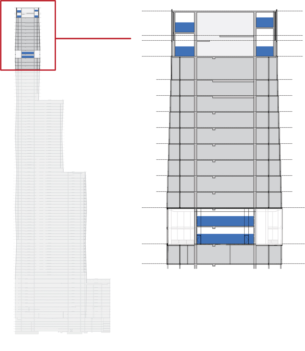
Tuned liquid sloshing damper tank layout.
In a further attempt to optimize the lateral bracing system, a final round of wind tunnel testing was conducted to evaluate multiple concepts representing minor but impactful geometric changes. One concept stood out as a clear winner: an upper-story blow-through level. The 87th story is 28 feet tall and clad with a grill that will appear solid from the ground while allowing wind to pass through the tower at this elevation. The blow-through effect directly relieves a portion of the wind force but also disrupts the flow and amplitude of wind forces for several stories above and below. Along with the switch to porous roof screens, the net effect of the blow-through level is a 24 percent reduction of the cross-wind lateral response.
A Vision Realized
An iconic building geometry enhances a city’s skyline, inspires all who see it, and increases a developer’s end value. However, a great design is only great if it is built. This poses the challenge to a structural team to deliver a building that meets the developer’s pro forma requirements and utilizes an arrangement of elements that can be practically constructed, all without compromising the original architectural vision. MKA’s design of Vista Tower has realized these goals, integrating the need for open floor plans and a diverse building program with the robust structural frame necessary to support and keep stable this super-tall tower. The never-before-seen alternating-stacked frustum geometry of Vista Tower is now rising quickly on the Chicago River.▪