
When damaged members and connections are identified, it is imperative to assess the extent that the damage may impact the structural integrity of the cold-formed steel member or connection. As stated in the Engineers Notebook article, Evaluation of Cold-Formed Steel Members and Connections (STRUCTURE, February 2018), assessment should be made quickly to contain the damages or protect the public welfare.
Remediation of damaged cold-formed members and connections may include the following.
Repair of Damaged Coating
Because of the galvanic action provided by the zinc coating, AISI S200, North American Standard for Cold-Formed Steel Framing – General Provisions, states that additional corrosion protection shall not be required on edges of metallically coated steel framing members that are shop or field cut, punched, or drilled. Thus, small scratches or abrasions in the galvanized coating need not be of concern. Zinc-rich paint may be used to remediate larger damaged areas of the coating.
Damage to the Coating Caused by Welding
AISI S200 stipulates that, for welded connections, the weld area is to be treated with an approved treatment to retain corrosion resistance. However, based on when a weld area is not directly exposed to the environment, for example, a weld in the cavity of a properly constructed weather-tight wall or roof, remediation of the coating may not be required.
Damage Caused by White Rust
White rust is characterized by the formation of a light film of white powdery residue and frequently occurs on galvanized products. Provided the steel members are well ventilated and well-drained, white rust rarely progresses past the superficial stage. It can be brushed off but will generally wash off in service with normal weather. No remedial treatment is usually required.
Damage Caused by Red Rust
Red rust areas, usually a sign of extensive damage, if not treated, may progress to an undesirable stage and therefore should be wire brushed and the damaged area coated with a zinc-rich paint.
Repair of Screw Connections
The available strength of a screw connection may be evaluated using the provisions of Section E4 of the North American Specification for the Design of Cold-Formed Steel Structural Members, AISI S100. In addition to these provisions, AISI S200 provides additional guidance based on the in-place conditions of the connections, e.g., stripped screws, screw spacing, edge distance, etc. To estimate the strength of a screw, refer to CFSEI TN F701, Evaluation of Screw Strength.
Common problems affecting the capacity of screw connections include:
Screw Pattern
The AISI framing standards are silent regarding the influence that the screw pattern may have on the available strength of the connection. Research by Sokal and LaBoube has shown that the screw pattern did not influence the available strength of a connection. That is, if the screw connection requires 8 screws, the pattern 2 rows of 4 screws, 4 rows of 2 screws, or screws randomly located achieved the same available strength. This is predicated on proper spacing of the screws as required by AISI S100.
Screw Spacing
AISI S100 stipulates that the center-to-center spacing of screws must be at least 3 times the nominal diameter of the screw. However, where the center-to-center spacing of screw fasteners is less than 3 times the nominal diameter but greater than or equal to 2 times the nominal diameter, screw fasteners shall be considered 80 percent effective per AISI S200. Thus, a 20 percent reduction in capacity results with closely spaced fasteners. For connections with closely spaced screws, additional screws may need to be added to the connection to achieve the desired design capacity.
Stripped Screws
The impact of a stripped screw in a connection depends upon the force being transferred by the screw. AISI S200 provides guidance for assessing the impact of stripped screws. For stripped screws in direct tension, the screw is not to be considered effective. Thus, additional screws must be added to the connection. However, for stripped screws in shear, as many as 25 percent of the screws in the connection may be stripped without a loss in connection capacity. If more than 25 percent of the screws are stripped, additional screws must be added to achieve the desired capacity.
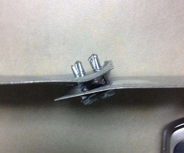
Gap between connected members.
Gaps between connected members may be a problem and should, if found to affect the capacity of the member or connection, be remediated. When connecting two members, AISI S200 stipulates no separation be present between the components. However, no separation is sometimes difficult to achieve. Tests at both Virginia Tech and the University of Missouri-Rolla have shown that a separation or gap of 0.15 inch is possible with minimal degradation of the connection strength. Thus, a small gap, for example, equal to the thickness of the thinnest ply, may be deemed acceptable. Therefore, it is suggested that when evaluating the strength of a screw connection using AISI S100 Section E4.3, the criteria shown in the Table should be used.
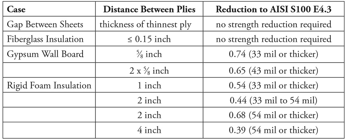
Table of criteria for evaluating the strength of a screw connection.
Remediation
Be Wary of Loaded Members
When members or connections are under load, the remediation plan must consider the impact of any remediation activity. For member design that utilized the sheathing as a brace, proper bracing of the member must be maintained if the sheathing material is to be removed during the remediation activity. For example, to maintain a member for full yield moment capacity, Maxo, bracing intervals should be less than or equal to Lu where Lu is defined by AISI S100 Commentary Eq. C-C3.1.2.1-11.
Consider the Type of Remediation Carefully
The use of screw connections is preferable to welding if the wall, floor, or roof cavity has insulation or other combustible materials. Screw connections may be preferable to bolted connections because of the difficulty with drilling bolt holes.
Temporary Supports
Scaffolds must be engineered and designed to adequately and properly support existing members and connections in a manner that will not compromise the structural integrity of the cold-formed steel framing.▪
References
(AISI S100-12), North American Specification for the Design of Cold-Formed Steel Structural Members, 2012, American Iron and Steel Institute, Washington, D.C.
(AISI S200-14), North American Standard for Cold-Formed Steel Framing – General Provisions, American Iron and Steel Institute, Washington, D.C.
(AISI S202-14), Code of Standard Practice for Cold-Formed Steel Structural Framing, American Iron and Steel Institute, Washington, D.C.
Sokol, M.A., LaBoube, R.A., and Yu, W.W. (1999), “Determination of the Tensile and Shear Strengths of Screws and the Effect of Screw Patterns on Cold-Formed Steel Connections,” Civil Engineering Study 98-3, Cold-Formed Steel Series, Center for Cold-Formed Steel Structures, University of Missouri-Rolla, Rolla, MO., 1999.
TN G500-11, Guidelines for Inspecting Cold-Formed Steel Structural Framing in Low-Rise Buildings, Cold-Formed Steel Engineers Institute, Washington, D.C.
TN G900-08, Design Methodology for Hole Reinforcement of Cold-Formed Steel Bending Members, Cold-Formed Steel Engineers Institute, Washington, D.C.