
The Wahweap Marina Store is located in the Wahweap Marina on the south end of Lake Powell, just south of the Arizona-Utah border near the beginning of the Grand Canyon. Situated between the docks and houseboats, the Wahweap Marina Store is a 10,144-square-foot floating platform that supports a 6,655-square-foot convenience store, restaurant, and office space. The second floor of the structure consists of a 1,425-square-foot covered deck that allows visitors to relax and enjoy their surroundings.
This floating facility has been designed to meet the long-term needs of the owner in their specific areas of operation and service, as it accommodates the constantly changing water levels of the lake.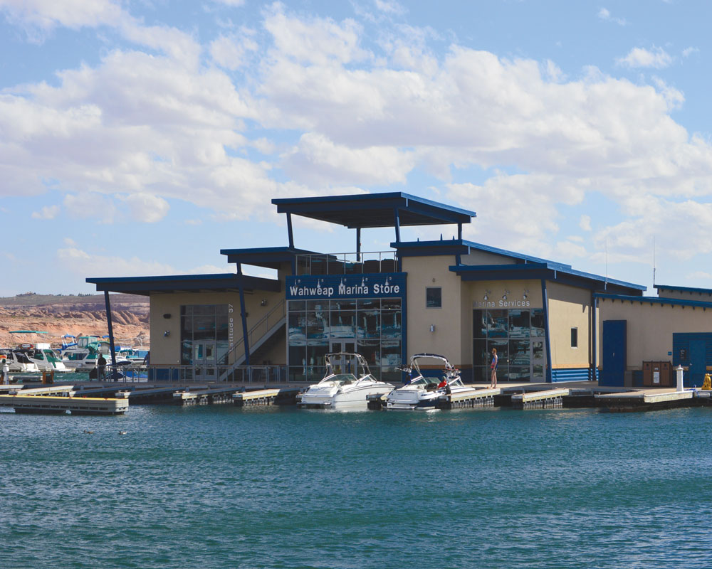
The Challenges
The owner needed a space that could handle the various services offered. There were several challenges that the design team faced:
- The structure was required to house office space for boat rentals, restaurant space, and a convenience store for groceries and other retail goods. All of this needed to fit within the existing docks where houseboats are moored year around.
- A storage space within the facility was essential. The owner needed to have the ability to store additional merchandise on site and limit the number of trips transporting goods along the docks.
- The final freeboard elevation of the structure needed to align with the adjacent docks, and at an elevation where small watercraft could dock with bumpers and occupants could easily enter and exit their boats.
- Determining construction sequencing of the float system, with ballasting and launching restrictions, was crucial to the design. The structure needed to be constructed during the tourism off-season so that it did not interfere with boat launch ramps and visitor parking. Deciding how to launch the structure, and when and where to build each section of the structure, was discussed at length.
Designing the Flotation System
The facility has been designed to accommodate the constantly changing water level of the lake. Previous projects with this client have incorporated the use of long cylindrical tanks that can be filled with water (as needed) to buoy up and ballast the floatation system. For this project, the owner requested that a mechanical room and storage room be placed beneath the structure and that all of the ducts, piping, and sump pumps be placed within this space. The owner needed a maximum of 28 inches of freeboard (distance between the top surface of the walking deck and the top surface of the water) to allow for neighboring docks to be attached at similar levels and to allow boats to pull up to the walkway. Creating a storage area that was too deep would produce too much buoyancy, making it difficult to tie the platform to surrounding structures. Steel truss systems were used in the design of the deeper storage section of the hull to transfer forces throughout the structure, increasing global stiffness and meeting the required buoyancy objectives. The “T” shaped hull section was designed to mitigate any warping or twisting of the platform with the changing loads.
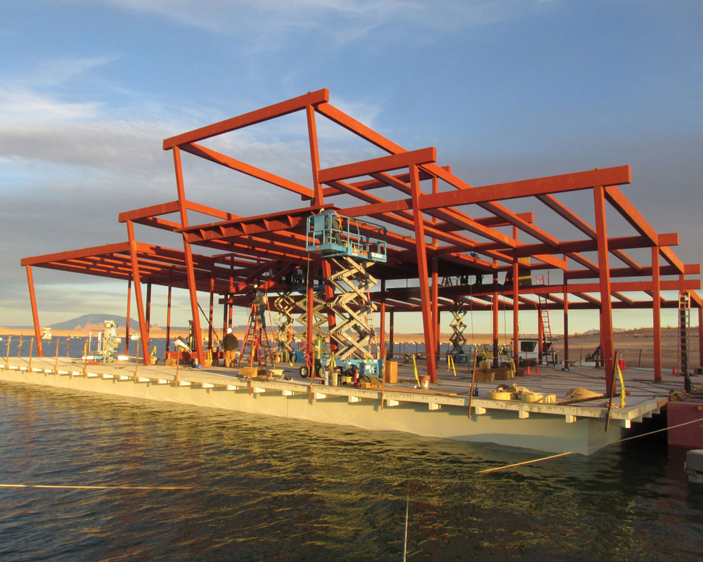
Figure 1. Structural steel framing for the Wahweap Marina Store.
To verify the hull was watertight, the exterior shell plates were continuously welded together. The construction documents indicated that the contractor was to test the welds for leaks using soapy water and compressed air and to repair any locations where bubbles formed. As a back-up, a system of sump pumps was installed throughout the hull.
The design of the floatation portion of the structure is based on Archimedes’ principle that any object, wholly or partially immersed in a fluid, is buoyed up by a force equal to the weight of the fluid displaced by the object. More simply put, the buoyancy of the hull supporting the structure is equal to the weight of the displaced fluid. Therefore, it was imperative that all dead and live loads on the structure were accounted for and that the water displaced by the hull was accurately calculated. Designing the supporting structure to meet a minimum dead and live load criteria prescribed in the code works great for typical buildings with foundations. Using these same design loads also works well for designing the components of the structure. However, to accurately determine the buoyancy of the hull and the amount of freeboard during operation is a different matter. To understand the different freeboard levels in the water, a spreadsheet was created to consider 4 different load combinations to maintain the 28 inches (maximum) of freeboard that the owner was requesting. Utilizing simple graphics showing the changes in freeboard assisted the team in determining realistic freeboard elevations for planning and installing the floating docks around the new facility (Figure 2).
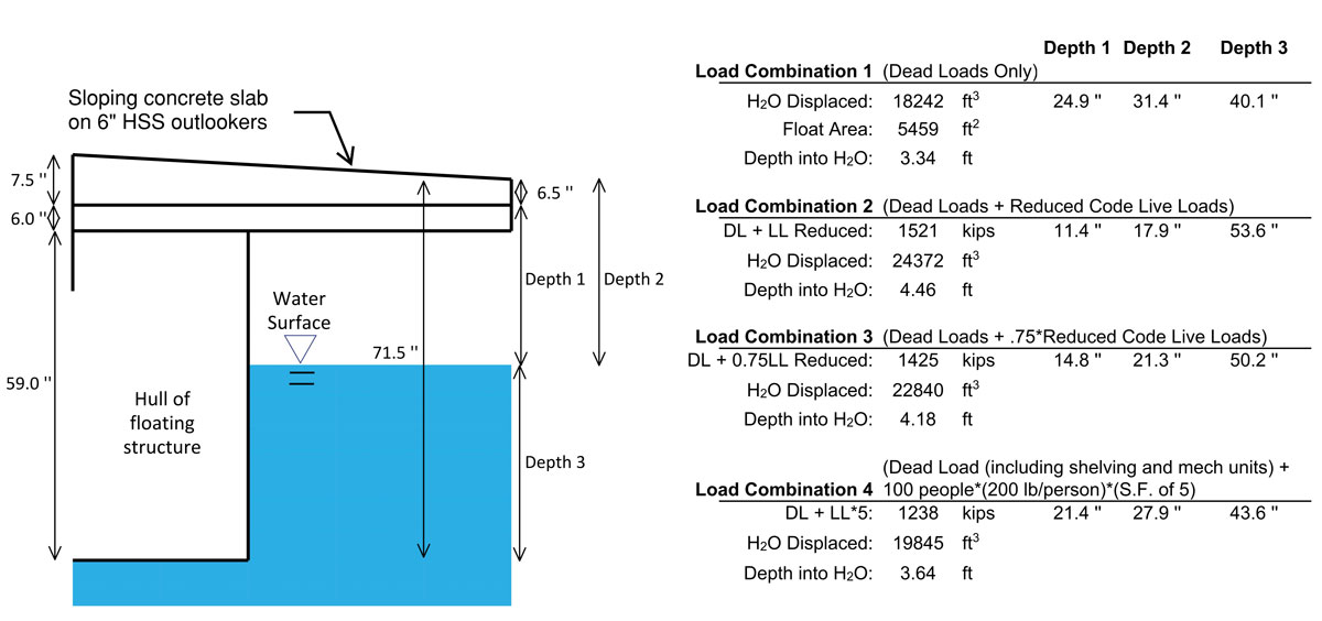
Figure 2. Example of the buoyancy calculation.
Launching a Building
There were many discussions regarding the means and methods of launching a building of this size and complexity in such a remote location. Historically, there have been years where the water levels of the lake have risen 12 inches per day during springtime runoff. One option for construction was to build the hull of the structure on or near the ramps at a water level elevation the lake would likely reach in the spring based on historical data. In retrospect, the designers were thankful that option was dismissed. The winter when construction occurred was a drought, and the water levels never approached the proposed historical water elevation at which the hull would have been built.
It was decided that the hull would be constructed at the top of the boat ramp in the parking lot and launched before the concrete deck was poured and the steel structure above was erected. The hull portion of the structure was constructed using wide-flange beams and HSS beams that were designed as a truss system to distribute loads throughout the platform evenly. This “T” shaped floatation system is approximately 8 feet deep in the middle section and 5 feet deep in the side sections.
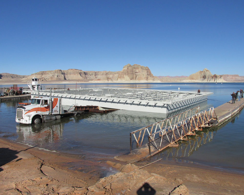
Figure 3. The platform being launched from the boat ramps into Lake Powell.
The sides and bottom of the floatation’s structural hull are covered with ¼-inch and 5⁄16-inch steel plates and angles, and the top of the flotation structure consists of a sloping 7½-inch suspended concrete slab on metal deck. The lower section of the hull houses all of the mechanical equipment and also doubles as a storage room. The upper structure consists of exposed HSS beams and battered columns that project away from the building and provide the lower deck with shade. The point loads from these columns are transferred to the truss system and distributed across the hull. The upper patio area is constructed with a 4½-inch suspended concrete slab on metal deck with a covered steel roof system above. Wood-sheathed steel stud shear walls provide lateral resistance. In the freshwater-marine environment, the owner found that painting exposed steel and maintaining the building envelope was adequate to mitigate the corrosion of the structural hot rolled and cold-formed steel.
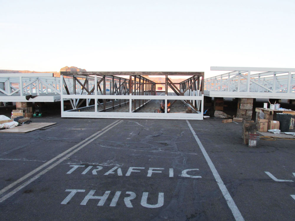
Figure 4. A section through the hull as it was being fabricated on the launch ramp.
Shortly after the hull was launched, the contractor called to explain that the deeper 8-foot “T” portion of the structure was so buoyant that the two 5-foot-deep sides of the hull were not touching the water (Figure 5). This construction issue was quickly remedied by temporarily filling the lower 8-foot-deep portion of the hull with water so as to not cause reverse loading of truss members within the hull.
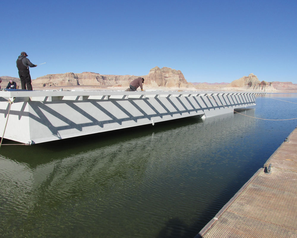
Figure 5. The deeper section of the hull was so buoyant that the shallower sides are suspended above water shortly after being launched.
This allowed the suspended W-2 deck and concrete topping slab, that covers the hull and acts as the floor for the store, to be poured without causing damage to the truss members. Careful consideration was taken in pouring the 10,144-square-foot suspended concrete floor. It was poured systematically to mitigate torsion in the structural members and to keep the platform level.
Initially, the owner wanted to build steel ballast tanks in strategic locations throughout the hull structure to counterbalance any heavier sections of the building and help keep the overall structure level on the water. Once the building was constructed, a concrete topping slab was placed within the 8-foot-deep section of the hull. At this point, the building sat level on the water and the owner decided that the expensive ballast tanks and drainage systems were no longer needed and could be omitted.
The new facility is now located on the same site as the original facility that was constructed in the early 1960s and had experienced several additions and renovations over its 50-year life. The original facility had little or no storage space, had deficient mechanical systems, and only had a small convenience store; hence the replacement. The construction process undertaken with the new convenience store allowed the majority of the new facility to be constructed away from the site and moved into place after the existing building was disconnected from the docks and removed. This construction sequencing allowed for the continual operation of the existing facility while construction of the new facility was occurring nearby. As a result, marina patrons enjoyed minimal disruption in services.
Being involved from the early programming stages of the project allowed the design to evolve, with all consultants contributing to arrive at the best solutions. Pooling together all resources necessary to meet deadlines, along with continual construction administration throughout the building process, helped ensure a successful outcome.▪
Project Team
Owner: Aramark, Wahweap Marina
Structural Engineer: ARW Engineers, Ogden, UT
General Contractor: Lake Powell Construction, Page, AZ
Architect: VCBO Architecture, Salt Lake City, UT