
Innovative Erection Procedures for the Milwaukee Avenue Bridge
Originally a railway line developed in 1873, the Bloomingdale Line carried passenger and freight trains from the near north side of Chicago 35 miles out to the western suburbs. In 1910, a portion of the line in Chicago was elevated to help reduce pedestrian accidents at street crossings. By the late 1990s, rail traffic on the line had declined substantially, eventually halting in the early 2000s. The railway line sat largely abandoned until 2013 when the City of Chicago purchased a 2.7-mile segment of the railroad right-of-way and engaged Walsh Construction (Walsh) to develop this segment into The Bloomingdale Trail and Park, also known as “The 606.” This adaptive reuse project turned the railway into a landscaped elevated park for walkers, runners, and bikers, connecting multiple city neighborhoods and spurring economic development.
The 606 repurposed more than 30 of the original steel bridges or concrete viaducts, including perhaps the most iconic component of The 606. The bridge over Milwaukee Avenue took a former four-span, simply-supported bridge and converted it into a single-span, tied-arch bridge. The Engineer of Record for the project was Collins Engineers Inc.; Wiss, Janney, Elstner Associates Inc. (WJE) served as the construction and erection engineer, assisting Walsh with an innovative erection plan for the bridge.
Existing Four-Span Bridge
The original four-span bridge over Milwaukee Avenue was 26 feet wide by 98 feet long and had a skew of approximately 45 degrees (Figure 1). The structural framing consisted of a reinforced concrete deck on top of transverse steel floor beams that spanned between three main longitudinal built-up, riveted steel plate girders. The girders were simply-supported by three interior steel piers and two reinforced concrete abutments.
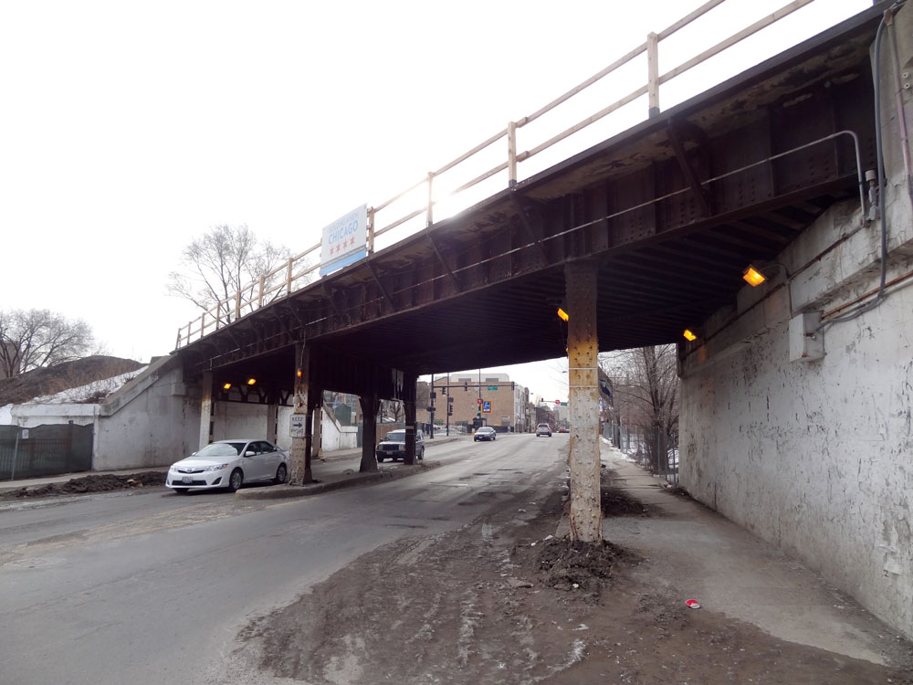
Figure 1. Existing bridge structure.
The existing reinforced concrete deck was removed and, since the anticipated loads for the new trail were significantly less than train loads, approximately two-thirds of the existing steel floor beams were also removed. Next, localized structural repairs were made to the main longitudinal steel girders, primarily to address areas of corrosion-related deterioration that had occurred over the 100+ year life of the structure. Once repairs were installed, the entire structure was sandblasted and primed. Final painting occurred after the new bridge was fully erected.
Jacking Procedure for the Existing Bridge
To improve vertical clearance on Milwaukee Avenue, the final elevation of the new bridge needed to be approximately 3 feet 6 inches higher than the original elevation of 13 feet 6 inches. A jacking procedure was developed to lift the bridge off of its existing bearings up to its design elevation. The procedure began with the installation of new web splice plates and new top and bottom flange splice plates to make the simply-supported longitudinal girders continuous from abutment to abutment. The newly established continuity reduced the number of required jacking points from 24 (one at both ends of each simply-supported girder) to 12. The end spans of the girders cantilevered out past the interior jacking points, allowing unencumbered access to the existing reinforced concrete abutments and helping to facilitate the concrete repairs and new bearing installation. In general, the jacking procedure involved installing jacking towers and hydraulic rams underneath the longitudinal girders adjacent to the interior pier supports. The hydraulic rams – linked by a manifold – lifted the bridge from the piers and abutments in ¼-inch increments, while ¼-inch shims were placed on the piers. This limited the amount of displacement that would occur if hydraulic pressure was lost. As the hydraulic rams approached their full stroke (approximately 18 inches), they were locked into position; the shims were removed and new temporary steel shoring stools were installed on top of the piers. The girders were then lowered and secured to the new stools. Next, the hydraulic rams were relieved and a new custom jacking stool was placed underneath each ram. This lifting process continued until the bridge was raised to a height slightly above the final design elevation. New shoring stools, dimensioned such that they would support the girders at the final design elevation, were installed on top of the piers. The bridge was lowered and secured onto the new custom shoring stools, and then temporary diagonal bracing was installed to maintain a laterally braced structure during for remainder of construction. The elevated structure is shown in Figure 2.
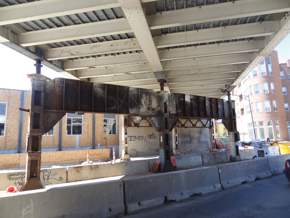
Figure 2. The elevated bridge structure.
Erection Procedure for Arch Assembly
Costs and logistical considerations for installing shoring and falsework over the busy Milwaukee Avenue corridor led the construction team to explore other innovative alternatives for erecting the three steel arches atop the in-place bridge. Ultimately, the team obtained permission to erect the arches in an adjacent grocery store parking lot and then lift the entire arch assembly from the parking lot to the existing elevated bridge structure. Each arch consisted of three separate HSS steel tube pieces that were laid horizontally and field-welded together. After all three arches were fully assembled, the first arch was tilted vertically using a crane and placed on top of horizontal steel HP sections – laid out to match the intended configuration of the bearing assemblies on the final bridge. A second crane tilted the second arch vertically and placed it on top of the steel HP sections. New steel cross framing was installed between the first and second arches. The third arch was installed similarly (Figure 3).
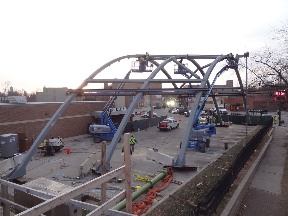
Figure 3. Erecting the three-arch assembly.
Lifting the Arch Assembly
Interferences and crane limitations prohibited the assembly to be moved directly from the parking lot to the bridge, so it was done in two stages. First, the crane was placed in the parking lot and attached to the three-arch assembly at four points – two near the peak of each exterior arch (Figure 4). The three-arch assembly was lifted onto temporary timber bearing pads located adjacent to the existing bridge structure. Second, the crane moved to Milwaukee Avenue and the three-arch assembly was lifted off the timber mats, placed onto the elevated bridge structure, and bolted to the top flanges of the existing longitudinal girders. The flexibility of the arch assembly allowed the erection team to move the base plate connections into alignment with relative ease.
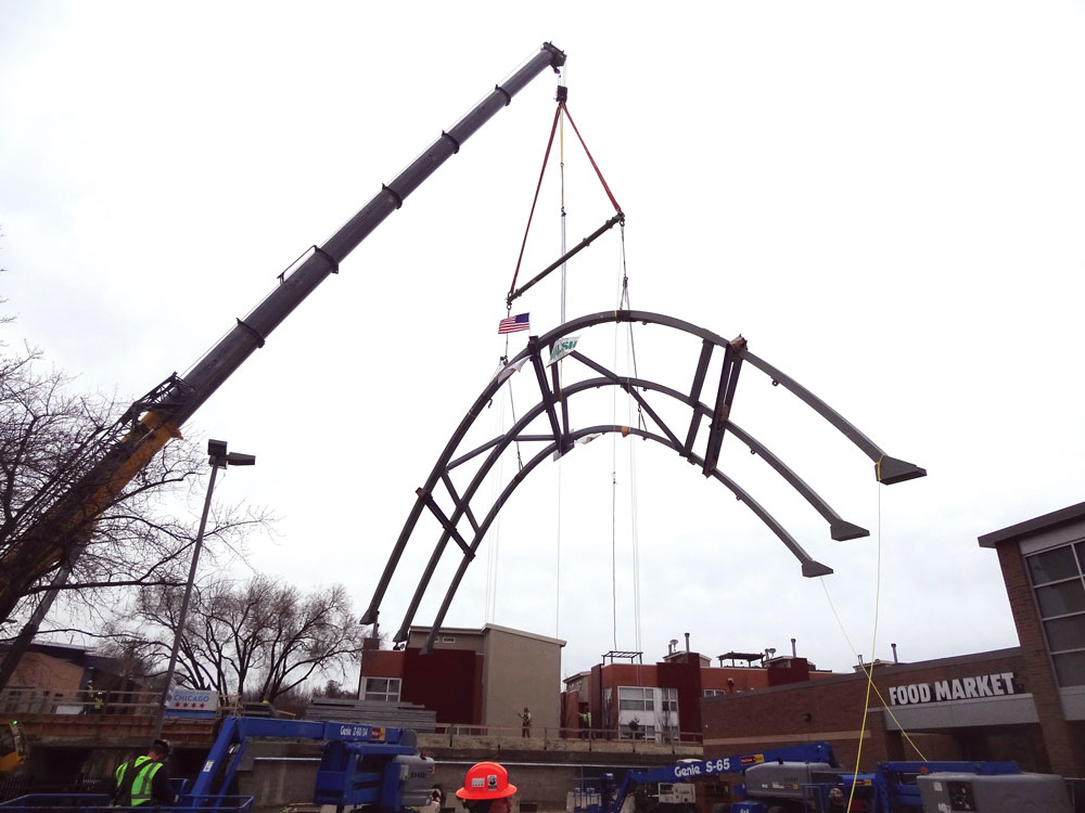
Figure 4. Lifting the arch assembly.
Tensioning Procedure for Arch Assembly
Installing and tightening steel cables to suspend the continuous longitudinal girders of the bridge, enabling the removal of all three intermediate pier supports beneath the bridge, was the final step. Clevises secured cables to the arches and a custom socket secured them to the longitudinal girders. The girders were disconnected from the shoring stools on the piers and tensioning occurred in each cable over the course of three iterations, each iteration adding approximately one-third of the full target load. “Full” load was intended to include all dead load plus some additional pretension as specified in the bridge design documents. Each socket was tensioned using a custom steel fixture and two calibrated load cells. The custom steel fixture and load cell assembly was designed to bypass the socket nuts (Figure 5).
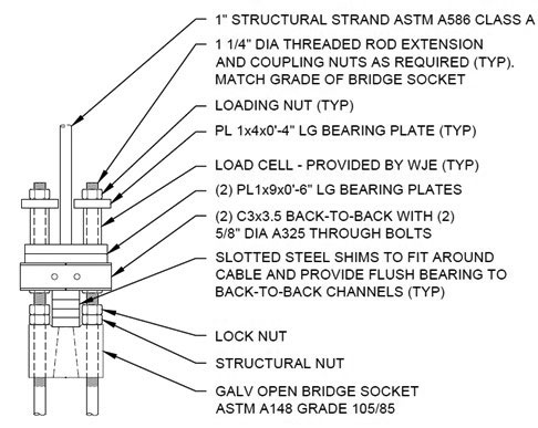
Figure 5. Custom steel fixture and load cell assembly.
Separate loading nuts on top of the steel fixture and load cell assembly were turned, approximately in unison, to add tension to the cable until the target load was reached. Socket nuts below the custom fixture were tightened against the socket, again approximately in unison, until the readouts from the load cells were reduced to zero, thereby transferring the load to the socket nuts (Figure 6).
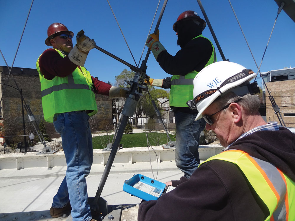
Figure 6. Tightening a cable and reading the load.
After two iterations of tensioning, the bridge lifted off of the temporary shoring stools. A third iteration added pretension to the cables. A final pass recorded the actual load in the cable by installing the custom steel fixture and load cell assembly and tightening the loading nuts until the washers beneath the socket nuts became loose. The load in each load cell was recorded, and the socket nuts were tightened until the load in each load cell returned to zero to transfer load back. With the bridge spanning between the abutments, the existing steel piers were removed and the final coat of paint was installed.
Summary
Enjoyed by hundreds of thousands of recreational users since its opening in June 2015, the new “606” path is a creative repurposing of an existing, abandoned railway line. The newly adapted Milwaukee Avenue Bridge is a signature element of the trail. In recognition of the innovative design and construction techniques, the bridge won the 2016 National Steel Bridge Alliance award for Special Purpose structures.▪