
Samuel Keefer’s suspension bridge that opened in 1868 just below the Falls of Niagara was replaced by the Niagara-Clifton Steel Arch Bridge. Leffert L. Buck (STRUCTURE, December 2010) replaced Keefer’s wooden towers with iron and later replaced and widened the wooden suspended structure with iron in 1888. When the suspended deck structure of his replacement bridge blew down in a wind storm on January 9, 1889, Buck was retained to design and build the replacement structure, which opened on May 7, 1889. Again in 1895, he was called in to design a new bridge at the site because the bridge company wanted to run electric trolleys over it.
In selecting an open-spandrel arch form, Buck decided “to brace the ribs instead of the spandrels of the arch.” He doubted “whether a braced-rib arch is as economical as a braced-spandrel arch where the latter form can be adopted,” and [he believed] “that the latter form can be made much more graceful than the former, though opinions differ as to their comparative beauty.” It would be the longest arch bridge in the world at the time, exceeding Gustave Eiffel’s Duoro Bridge in Portugal by almost 50%. Buck chose the braced-rib arch for the following reasons:
- The long span of the arch resulted in the braced-rib arch being less expensive.
- The deck floor could not be level because of the difference of elevation of the ground on the opposite sides of the gorge, so the arch could not be symmetric.
- This form of an arch would not intercept the view of the falls from points below. In other words, the vertical and horizontal web pattern for the braced-rib arch would not be as solid looking as that of a spandrel arch.
- It would reduce the load that the anchorages would have to resist due to the dead load of the arch prior to when “the parts met and became self-sustaining.”
Having chosen the braced-rib design, Buck then worked out a plan that would maintain (as close as possible) the existing alignment of the suspension bridge and its connecting roadways and future trolley lines. On the Canadian side of the bridge, he could maintain the centerline precisely. However, on the American side, he had to deviate from the ideal line due to “the tail-race of the Niagara Company’s tunnel,” which was directly under the suspension bridge. This was not a problem for a suspension bridge with no supporting structures in the gorge, but would not permit the construction of the skewback foundations at the desired elevation (40 feet above mean high water) and position required for an arch bridge.
The bridge’s foundations for the skewbacks were founded on “boulders, ranging between pebbles and blocks of several cubic yards in size, closely and firmly bedded in a matrix of gravel.” Buck then, just as C. C. Schneider had done 12 years earlier at his cantilever bridge (STRUCTURE, September 2015) just downstream, built his “foundations of concrete, with flaring sides to give ample base, extending back to the vertical face of the solid rock.” It was necessary to go to solid rock to support the lateral thrust of the arches. He believed that “next to solid rock such a foundation of boulders and gravel is, perhaps, as secure as need be desired, fortified as it is by a backing of solid rock.” He extended his foundations with limestone from Chaumont, Canada, placed on the concrete until it reached the steel skewbacks. He began work on the foundations in September 1895 and completed them in June of the following year.
The superstructure, of braced-rib arches, was described by Buck as follows:
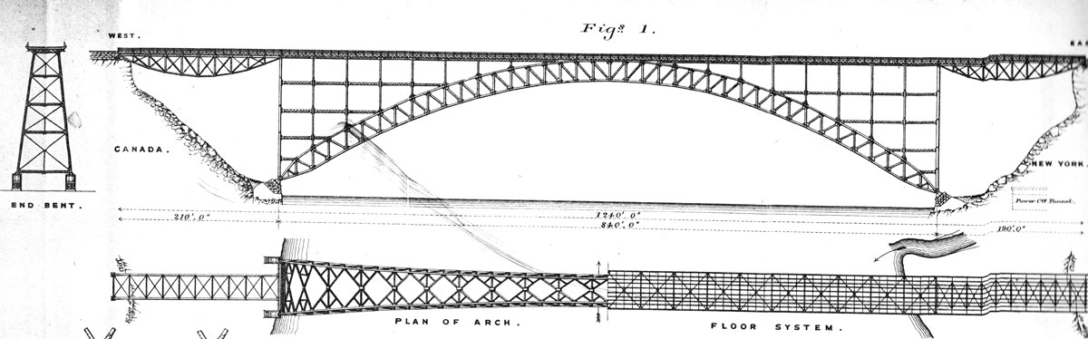
The span of the arch is 840 feet from centre to centre of the end pins. Its rise is 150 feet from the level of the end pins to the centre of the rib-trusses at the crown of the arch, measured vertically. The span is divided into twenty main panels of 42 feet each. The rib-trusses are battered at an angle with the vertical of 6°47’. The transverse distance from centre to centre of the end pins is 69.047 feet, and from centre to centre of the top chords at the middle of the span 30.25 [feet].
The top and bottom chords at the arch-ribs are united in solid web sections at 10 feet 6 inches from the centres of the end pins. The web-sections and the end posts bear on steel castings, which in turn bear on pins 12 inches in diameter and 5 feet 10 inches long. The pins are supported by cast-steel shoes, which rest on seats in built steel shoes arranged to distribute the pressure uniformly over the faces of the masonry abutments…
There are double systems of stiff laterals in the planes of both the top and bottom chords of the arch-ribs; these are reinforced by auxiliary braces, to reduce laterally their unsupported lengths. The main laterals are further supported at their intersections by vertical struts and diagonal rods, which come opposite the secondary panel-points. There are also heavier rods at the main panel points.
Finally, Buck built an inverted bow-string truss at each end of the arch to complete the bridge. He wrote that these “bow-string spans are not beautiful” but were the best solution as the rock under the shore end of the trusses was solid only near the surface. If he used a conventional parallel chord truss supported on its lower end panel points, he would have to cut through this rock and into underlying rock, which would “soon crumble and disintegrate.” The top chord of the bowstring served as part of the tie-back system adopted to erect the bridge.
Erection plan.
While the design of the bridge was exceptional, the erection techniques adopted were perhaps more exceptional. Traffic across the suspension bridge could not be interrupted to any significant degree while the new bridge was built under it. The erection, Buck wrote, “involved two main problems: first, to support the halves of the ribs without falsework until they met at the middle and, second, to overcome the interference between the old bridge and the new structure during erection…The arch was so high that its north rib interfered with both the stiffening-truss and the floor of the suspension bridge. It was desired to keep the old bridge intact as long as possible, for purposes of erection as well as for the maintenance of traffic.”
His solution was to build falsework from the bank out to a position just short of the skewbacks and build a tie back system from which ties could run down and support the arch as it cantilevered out over the river.
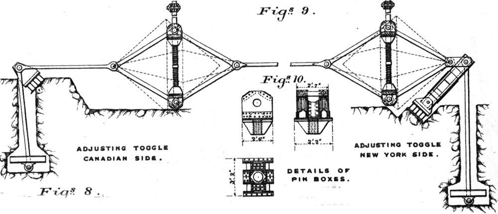
Toggle drawing.
He designed a toggle mechanism, along with its foundation, to apply tension to the main tie link which ran from the toggle to the top of the end vertical of the bridge. With this toggle, the entire arch could be lowered by simply letting-off on the toggle and if necessary, with more difficulty, lift the ends of the arch as required. The end vertical portion of the arch was also stiffened by building temporary cross bracing with the vertical placed over the second panel point. These diagonals would be removed after the arch closed.
The erection sequence was as follows:
When the anchorages and their connections were in position, the end bents of the main-span were raised and were connected with the anchorages. The first panels of the arch-span, 42-foot long, were then built out on each side of the river, resting on short bents of falsework in front of the abutments. When these panels were completed the first fore-anchorages A were connected, and by means of the adjusting links at a the weight of the panels were lifted clear of the falsework. Then the second panels, each 42 feet long, were built out and the second set of fore-anchorages were connected and adjusted. Thus the work was continued from both sides of the river to the middle.
Because the ends of the arch approached each other over the river with the center diagonals and lower chord in place, the toggles were loosened, and the ends of the arch came together at a pin. At this stage, the arch was a true three-hinged arch. The center top chords and the vertical member at the center of the arch were then riveted into place, leaving a gap for a jacking mechanism that Buck designed. In Buck’s words, the arch was “converted into a two-hinged arch by means of hydraulic jacks, with the top chords apart at the centre until the requisite stress for the amount of dead load then carried was imparted to them.” The gap between the ends of the top chord was three inches, which was “exactly as calculated.” He calculated that the top chord should have a load in it of 375,000 pounds and that the ends would have to be separated by 9 inches. After jacking the ends apart 6 inches, temporary shims were inserted to hold the ends apart “while permanent cast-steel blocks were planed to the correct thickness.”
After the blocks were ready, the jacks placed the specified load into the top chords. Once the jacks indicated the specified load, the temporary shims became loose and the permanent members were inserted, indicating to Buck “the accuracy of the calculations and of the shop work and the field measurements.” Buck wrote that he was “not aware of any other case in which the stress in a main member has been directly measured otherwise than by means of the strain.” After the top connection was made, the pin in the bottom chord was covered with a plate that was riveted into place thus making the structure a true two-hinged arch.
The replacement of the existing floor structure, supported by the suspension cables to the arch structure, was difficult due to the interference of the bottom chord of the suspension bridge and the top chord of the arch for a significant portion of the length of the structure. After considering several plans, Buck decided to remove “the entire stiffening-truss, except its top chords, and also the floor system of the old bridge together with auxiliary chords from these points (panel #14) to the centre, and to carry the travelers and a temporary floor directly on the cables. The top chords of the old stiffening-truss were kept intact to serve as a track for the traveler. Notwithstanding the removal of the stiffening-truss, the old bridge remained remarkably steady under the influence of wind and the concentrated loads imposed by the travelers, which weighed about 25,000 pounds each.”
The new floor system was put in, working from the middle of the river towards the shores. The travelers continued to be carried on the top chords of the old stiffening-truss. At the middle, the cables of the suspension bridge came below the top chords of the arch and there was serious interference between the south cables and the floor-framing and rib-laterals for the new work. Of course, the cables could not be removed until the entire stiffening-truss had been removed, and the latter was needed both for traffic and for transportation of materials. Therefore some of the top laterals of the rib at the middle were omitted, and a temporary floor-framing was arranged by building around the cables. When the permanent floor was completed on one side of the bridge, the cables were cut at the middle and removed… After the removal of the cables, the permanent floor system and omitted rib-laterals were finally placed in position. The floor beams and stringers were laid one panel at a time, 42 feet of the old stiffening truss being removed each time to make room for the new work. A small movable bridge was used to span the gap between the old work and the new while each panel length was being removed or constructed.
Work on the erection of the superstructure of the bridge began on March 1, 1898, and was completed by June 30 of the same year. The total project was completed on August 10, 1898. “The longest continuous period during which the traffic was stopped was about 3 days; the aggregate time during which it was interrupted was about 7 days. The celerity and precision with which the bridge was erected were largely due to the engineering staff and manufacturing department of the Pencoyd Ironworks, the contractors for the superstructure.”
The first electric streetcar crossed the bridge filled with dignitaries on June 30, 1898. The Niagara Gazette, in a first-page account, ran the headline “First Car across the Gorge.” It continued “the first electric car to cross the gorge and inaugurating international trolley traffic was car No.19 of the Niagara Falls Park & River Railroad which made the trip at 7:15 o’clock last night over the upper steel arch bridge. Only a few people, including the members of the press, were notified that the trip would be made and consequently the crowd to witness the first trip was not very great.” Richard S. Buck was on the first trip across the bridge along with the leaders of the railroad company.
The formal opening of the bridge to pedestrians and vehicles came on September 27, 1898. Between June 30 and September 27, trolley cars ran back and forth across the bridge on a regular schedule. With the completion of this bridge, Buck now could claim three of the sixteen longest arch bridges in the world, as well as three of the six longest arch bridges in the United States.
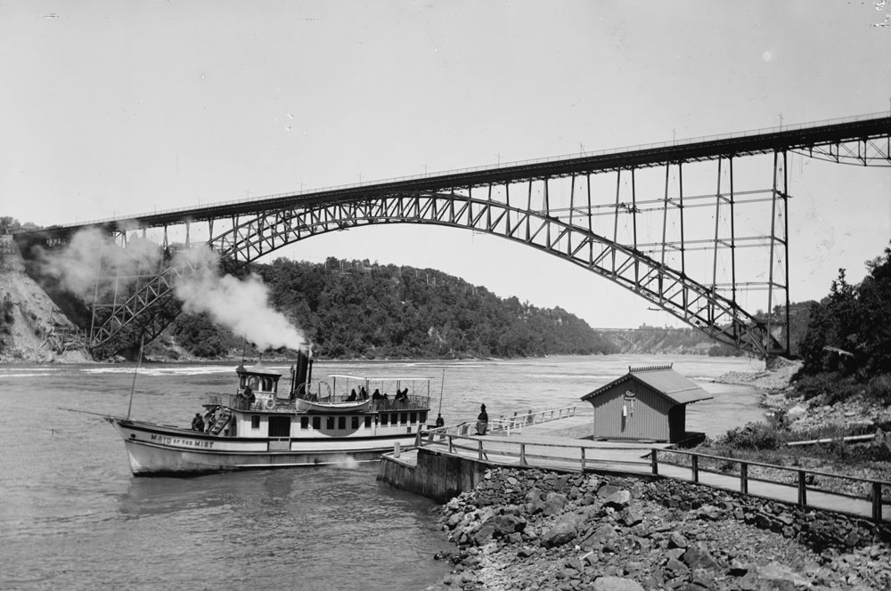
Completed Niagara-Clifton Steel Arch Bridge. Courtesy of HAER.
In 1900, Buck submitted a paper on this bridge to the Proceedings of the Institution of Civil Engineers, a British publication, entitled “The Niagara Falls and Clifton Steel Arch Bridge.” It is not clear why he chose to present the paper in a foreign journal rather than an American journal. Possibly it is because he had recently (December 1898) been granted membership in the Institution, still not a common thing for American civil engineers, and wanted to become better known to his British colleagues.
The bridge was taken out in an ice jam in 1939 and replaced by an arch bridge downstream by Waddell & Hardesty.▪