
When damaged cold-formed steel members or connections are identified, it is imperative they are assessed to determine the extent of the compromise to the structural integrity and the load carrying ability. Often, such assessment has to be made quickly to contain the propagation of damage to adjacent members and to protect the public welfare. Replacement of material is always an option. However, it may not be the most economical or expeditious solution.
For guidance on proper inspection considerations, the reader is encouraged to review the Cold-Formed Steel Engineers Institute’s (CFSEI) TN G500 Guidelines for Inspecting Cold-Formed Steel Structural Framing in Low-Rise Buildings. A summary of that document follows.
Use Uncoated Base Steel Thickness
The available strength of a member or connection is evaluated using the uncoated base steel thickness. The amount of coating is determined by coating weight, measured in ounces per square foot (oz/ft2). For example, a G60 coating indicates 0.60 oz/ft2. For the determination of base thickness for cold-formed steel coated material, 1 oz/ft2 = 0.00168 inches per the American Society of Testing and Materials’ ASTM A653. For this example, G60 coated sheet contributes 0.001 inches (0.60 x 0.00168) to the measured thickness.
Use Realistic Loads
Do not use conservative loads. For example, do not use a design load of 50 psf when 40 psf may be satisfactory per the American Society of Civil Engineers’ ASCE 7. Based on a study of actual floor loads, the American Institute of Steel Construction’s AISC Design Guide 11 recommends using a live load of 11 psf for office floors and 6 psf for residential floors when performing a floor vibration analysis.
Consider Using the Actual Yield Strength of the Member
When evaluating a member’s strength, it would be prudent to estimate, or determine by testing, the actual yield strength of the member. The American Iron and Steel Institute’s AISI S100, North American Specification for the Design of Cold-Formed Steel Structural Members, Chapter F, indicates that the mean value of the material factor, Mm, which is the ratio of the minimum specified yield stress to the as-delivered yield stress, may be taken as Mm = 1.10. Thus, for remediation computations, it may be permissible to use 1.10Fy. In fact, testing has shown that Grade 33 material is typically 40 to 45 ksi.
Damage to cold-formed members and connections can vary significantly in type and degree. CFSEI TN G500 provides guidance on evaluating the capacity of the member and connection. Common damage includes:
Large Web Holes
AISI S100 enables the strength evaluation of cold-formed steel members with web holes. For hole patterns that are not repetitive, as defined by the provisions of S100, the AISI S100 Commentary provides guidance regarding the use of a “virtual hole method” for assessing the available strength. CFSEI TN G900, Design Methodology for Hole Reinforcement of Cold-Formed Steel Bending Members, provides guidance for reinforcing.
Large Flange Holes
AISI S100 has specific design provisions in Section B2.2 for the evaluation of uniformly stiffened compression elements with holes. The specification is silent regarding holes in partially stiffened and unstiffened compression elements. In the absence of such provisions, one may consider applying the Section B2.2 provisions to partially stiffened and unstiffened compression elements. In such cases, the safety factor should be taken as 2.0 in accordance with AISI S100 Section A1.2.
For large holes in the tension flange, the nominal moment capacity may be evaluated using the following provisions of AISC 360-10, Specification for Structural Steel Buildings, Section F 13, Proportions of Beams and Girders:
If FuAfn ≥ YtFyAfg, no modification is required. Where Afn = net tension flange area, Afg = gross tension flange area, Yt = 1.0 for Fy/Fu ≤ 0.8, otherwise 1.1
If FuAfn < YtFyAfg,
Nominal Flexural Strength = Mn = (FuAfn/Afg)Sxt
Coped Web
A profile having one or more flanges removed results in a web element with a free edge. The available shear buckling strength for a web element may be determined by the provisions of AISI S214, North American Standard for Cold-Formed Steel Framing – Truss Design:
Coping is permitted in accordance with the following, as applicable:
a) At a coped support location with a coped flange and a bearing stiffener having a moment of inertia (Imin) greater than or equal to of 0.161 in.4 (67,000 mm4), the available shear strength [factored resistance] shall be calculated in accordance with Section C3.2 of AISI S100 and reduced by the following factor, R:
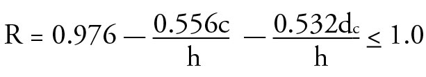
where
c = Length of cope
dc = Depth of cope
h = Flat width of web of section being coped
Imin = Moment of inertia determined with respect to an axis parallel to the web of the member
t = Design thickness of section being coped
b) At a coped support location with a coped flange where a bearing stiffener having a moment of inertia (Imin) less than 0.161 in.4 (67,000 mm4), the strength at the heel is governed by web crippling determined in accordance with Section C3.4 of AISI S100 and reduced by the following factor, R: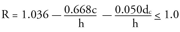
The above equations shall be applicable within the following limitations:
h/t ≤ 200,
0.10 < c/h <1.0, and
0.10 < dc/h < 0.4
Notched or Coped Flanges
A notched or coped flange may result in a free edge or an unstiffened compression flange element. The available member flexural strength may be computed by treating the flange as an unstiffened compression element in accordance with AISI S100 Section B3.1.
Member Splice
If it becomes necessary to splice two cold-formed steel members to achieve a desired member length, CFSEI TN W106, Design for Splicing of Cold-Formed Steel Wall Studs, offers design guidance. The two most common types of splices used in cold-formed steel construction are the “back-to-back splice” and the “track capped splice.” The design methodology presented in TN W106 is based upon the eccentrically loaded connection elastic method as presented in Part 7 of the AISC Manual as well as in Chapter 8 of Steel Design by William Segui.
Member Not Meeting Manufacturing Tolerances
If the cross-section profile does not comply with the AISI S200, North American Standard for Cold-Formed Steel Framing – General Provisions, manufacturing tolerances, careful measurement of the cross-section, and the application of AISI S100 provisions may be employed to determine the available strength.
Dings and Dents
Generally, small dings and dents have no impact on the structural integrity of a member; however, engineering evaluation is required when determining the impact of a ding or dent in a compression element of the cross-section. For example, if the flange or flange lip has been bent inward or outward, the member may be analyzed using the provisions of AISI S100 by utilizing the in-situ dimensions of the cross-section. Dings or dents in tension members are likely of little consequence on the available strength and can usually be discounted. During placement of a C-section, it may be possible to rotate the member and locate the ding or dent on the tension side of a flexural member or at a location of lesser applied moment.
In addition to evaluating a damaged member or connection and developing a remediation plan, responsibility for remediation should also be addressed and understood. AISI S202, the Code of Standard Practice for Cold-Formed Steel Structural Framing provides guidance pertaining to the responsibilities of the various individuals involved in the remediation work.▪
References
(AISI S100-12), North American Specification for the Design of Cold-Formed Steel Structural Members, 2012, American Iron and Steel Institute, Washington, D.C.
(AISI S200-12), North American Standard for Cold-Formed Steel Framing – General Provisions, American Iron and Steel Institute, Washington, D.C.
(AISI S202-15), Code of Standard Practice for Cold-Formed Steel Structural Framing, American Iron and Steel Institute, Washington, D.C.
(AISI S214-12), North American Standard for Cold-Formed Steel Framing – Truss Design, American Iron and Steel Institute, Washington, D.C.
(AISC 360-10), Specification for Structural Steel Buildings, American Institute of Steel Construction, Chicago, IL
(ASCE 7-10), Minimum Design Loads for Buildings and Other Structures, American Society of Civil Engineers, Reston, VA
Segui, W.T., Steel Design, 5th edition, Cengage Learning, Stamford, CT
TN500-11, Guidelines for Inspecting Cold-Formed Steel Structural Framing in Low-Rise Buildings, Cold-Formed Steel Engineers Institute, Washington, D.C.
TN 900-08, Design Methodology for Hole Reinforcement of Cold-Formed Steel Bending Members, Cold-Formed Steel Engineers Institute, Washington, D.C.
TN W106-15, Design for Splicing of Cold-Formed Steel Wall Studs, Cold-Formed Steel Engineers Institute, Washington, D.C.