
Column Transfers
A landmarked, 33-story steel moment frame building, 75 Rockefeller Plaza bookends the north end of Rockefeller Center. The building was originally constructed in 1947 for John D. Rockefeller’s Standard Oil Company and features the limestone and cast aluminum façade (Figure 1) that is emblematic of Rockefeller Center. A developer leased the building in 2013 and began a top to bottom renovation. Structural work occurred on every floor and included support framing for new elevators and mechanical equipment. A lobby reconfiguration required removal of four existing building columns on the ground floor. Three of these columns supported existing transfer girders at the second floor. This article focuses on the transfer of these columns, the structural solution constructability, and the load transfer procedure.

Figure 1. 75 Rockefeller Plaza seen looking north from the ice skating rink.
The columns scheduled for removal supported the full tributary load of the tower above, with a service gravity load ranging from 1,700 kips to 2,700 kips at the second-floor level. The design team considered several options to remove the columns from the double-height lobby before settling upon new transfer girders below the second-floor level. Each new transfer girder runs parallel to the existing transfer girder and effectively extends its span from 18 to 30 feet. Figure 2 shows a Second-Floor plan view, and Figure 3 shows an elevation of a new transfer.
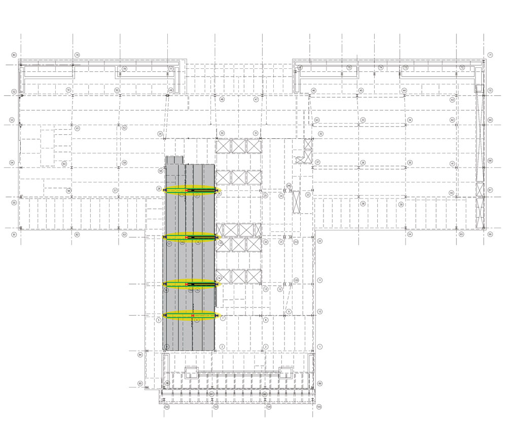
Figure 2. Second-floor framing plan highlighting the columns to be removed in red, the new transfer girders in green, and the existing transfers and column above in black.
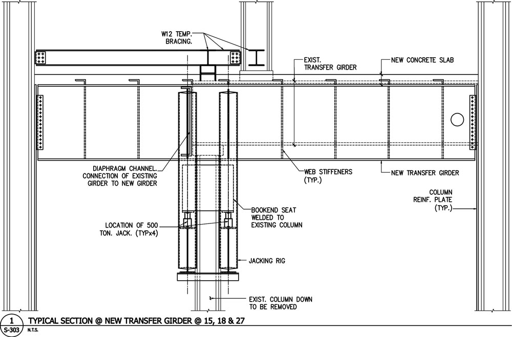
Figure 3. Elevation of the existing framing, new transfer girder, and jacking rig.
Schematic design began before the building could be accessed. The architect, the steel erector, and the general contractor provided early and consistent input to the initial design. To communicate the structural design concept, Gilsanz Murray Steficek, the structural engineer, printed a three-dimensional scaled model of the existing conditions and the new transfer girders. Each component was printed individually and connected with magnets, simulating the erection and preloading process. When access to the building was gained, and existing field conditions could be verified, lines of communication were already in place between the engineer, the general contractor, and the steel fabricator.
New Load Path
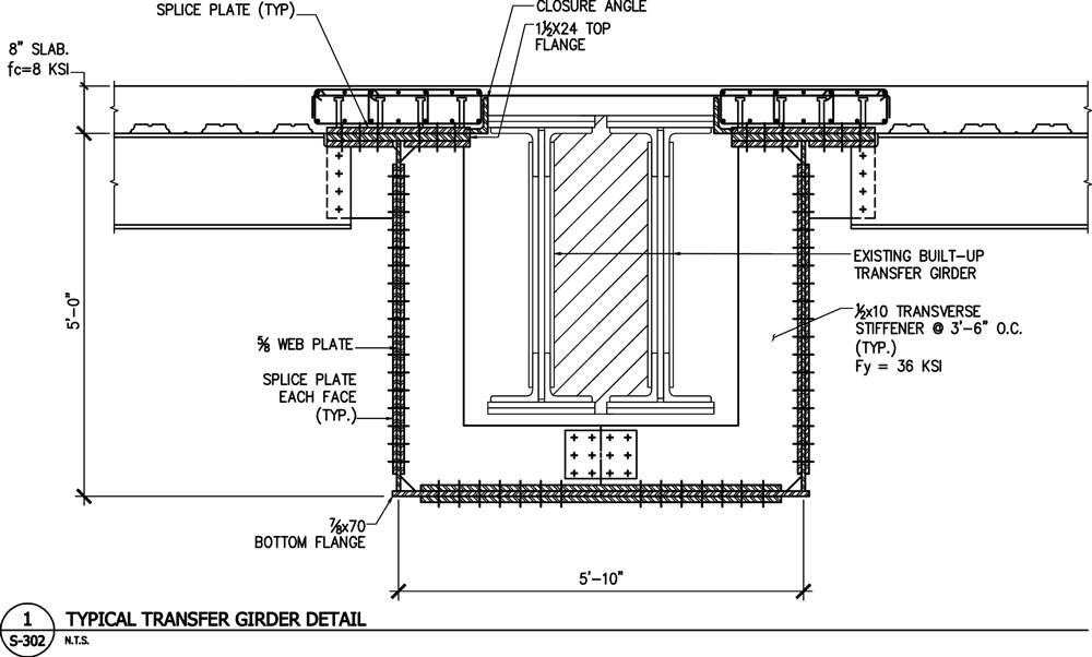
Figure 4. Cross section of the new and existing transfer girders.
The new transfer girder cross section (Figure 4) was shaped by architectural constraints, preloading concepts, constructability, and existing conditions. The architectural concept for the lobby, which includes a scalloped ceiling, limited both the depth of the new girder and its bottom flange width.
The new transfer girder was kept below the second-floor slab to preserve rentable square footage. At this level, the new transfer girder needed to fit around the existing girder, which is a pair of built up wide flange shapes.
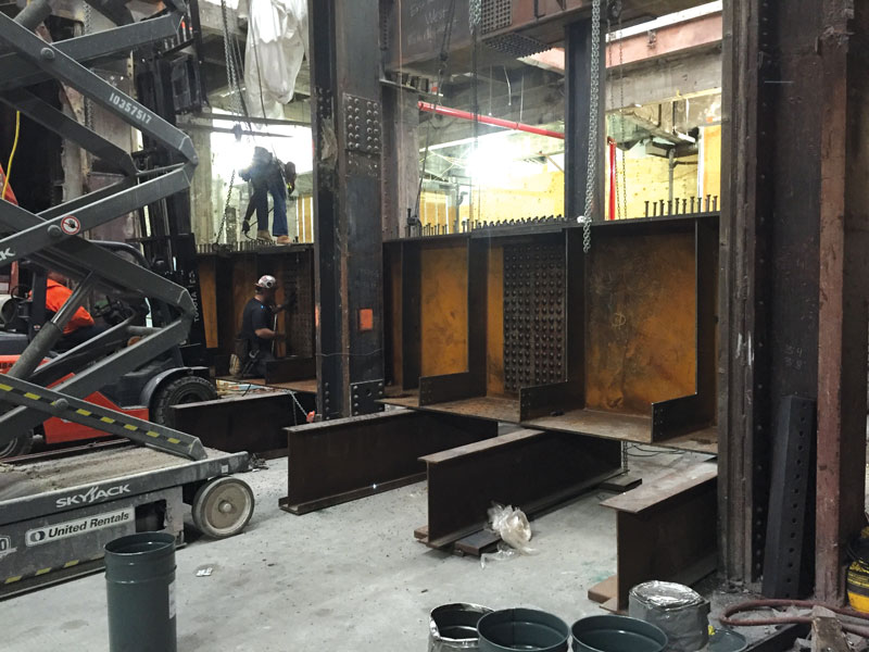
Figure 5. Half of the box being erected.
A composite box girder was used to meet these geometric constraints (Figure 4). Composite box girders are not common in buildings. The American Association of State Highway and Transportation Officials (AASHTO) code was referenced in addition to AISC 360, Specifications for Structural Steel Buildings, for analytical checks and dimensional requirements. The new girder webs are slender and transversely stiffened (Figure 5). The composite girder steel was sized to elastically resist the dead load, the reduced live load, and the induced load from the column jacking. The plastic capacity of the composite section was sized for the unreduced live load, providing reserve capacity.
The new transfer girder supports the existing structure at the end of the existing transfer girder. Connecting to the existing structure at this location, rather than at the location of the column above, limits the bending moment in the new girder by keeping the point load nearer to the end support. The magnitude of the point load at this location is equal to the end shear of the existing transfer girder, as opposed to the full axial load of the column above. A new built-up channel (Figure 3) picks up the webs of the existing transfer girder and spans between the new transfer girder webs. The connection between the channel and the new girder web was the final connection to be completed after the girder was preloaded and was made with a full penetration weld.
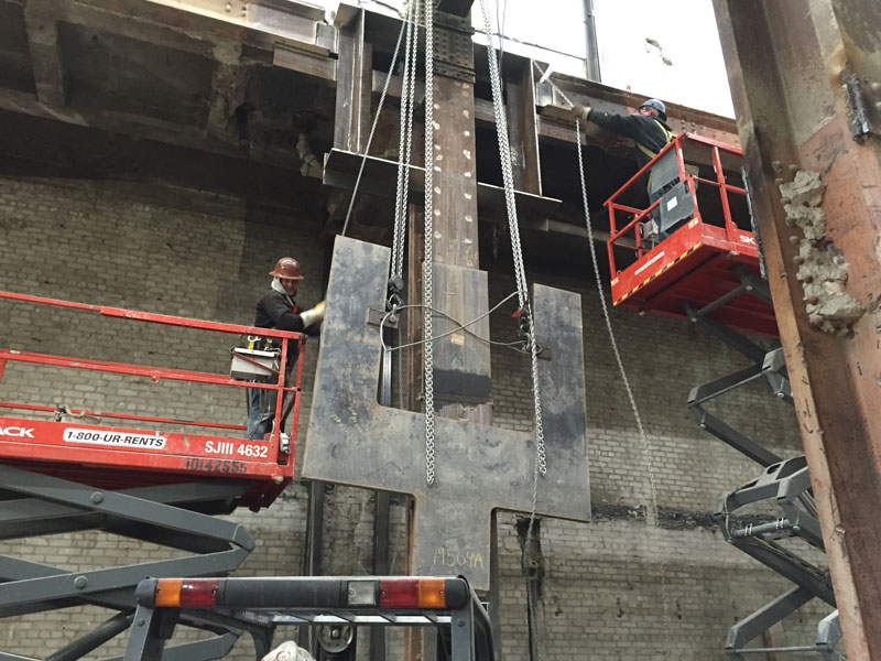
Figure 6. Column cover plate erection.
Following the new load path, the existing columns supporting the new transfer girders received approximately 50% more load and required reinforcing. Several columns were directly adjacent to existing elevator shafts, and access to reinforce their far flanges would have required shutting down the elevators. The columns were reinforced on one side with a single cover plate (Figures 6 and 7) to address this constructability challenge. The new cover plate was designed considering the elastic stress in the asymmetric column under a staged construction.
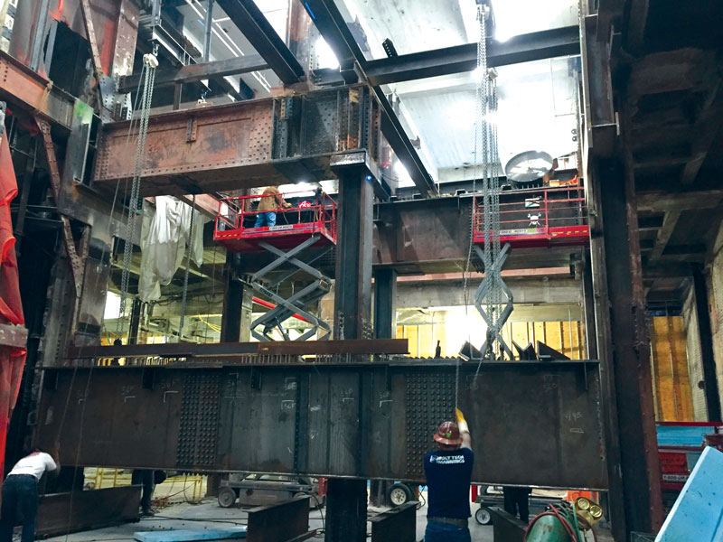
Figure 7. Transfer girder erection.
The new box girder webs are 68 inches apart. To connect the new girder to the reinforced column, the column cover plate widens at the top and forks around the existing transfer girder (Figure 7), where it is stiffened from behind with WTs (Figures 7 and 8). The box girder connects to the new cover plate with double angle connections, bolted to the girder webs and welded to the cover plate. One design concern at the new girder-column connection was the transfer of moment into the columns when the new girder was loaded and under varying live loads. Strength and Ductility Requirements for Simple Shear Connections under Shear and Axial Load (Thornton, 1997) was referenced to estimate the maximum moment the double angle shear connections transferred to the column. The depth of the new connections was limited to minimize the transferred moment; the reinforced columns and forked plate were designed for this moment.
The existing footings are steel grillages on rock. A geotechnical engineer was engaged to review the increased bearing pressure and it was determined that these footings have the capacity for the additional eccentric load.
The building’s lateral system is a partially restrained steel moment frame designed under the 1938 New York City Building Code. The 1938 code design wind pressures are much less than current standards. The 1938 Code specified no wind loading for the first 100 feet above grade and a 20 psf load above 100 feet. The base shear at 75 Rockefeller under the 1938 Code is 43% of that under ASCE 7-05 Exposure B. Removing four columns from the lobby and stiffening the adjacent columns modified the building’s lateral system slightly. Three-dimensional finite element models of the existing and modified moment frames were used to verify the modifications. These models determined the modifications did not significantly change the overall lateral stiffness and did not increase the relative demand on any existing connections by more than 10%.
Load Transfer
Pre-loading the new transfer girders using hydraulic jacks provided some advantages. It limited any permanent deflection of the floors above. In a moment frame structure of 75 Rockefeller, preloading limited the stresses induced in the frame when a single column was allowed to vertically displace. It also allowed the load transfer to be completed while the entire existing structure was in place, maintaining redundancy throughout the loading procedure.
The loading procedure is often dismissed by engineers of record as means and methods of construction handled by the contractor. However, the preloading can have significant structural effects. Coordinating a procedure with the contractor during the early design stages allowed the engineer to more accurately account for effects like moment transfer at the connections, column strain, and resistance from the existing moment frame.
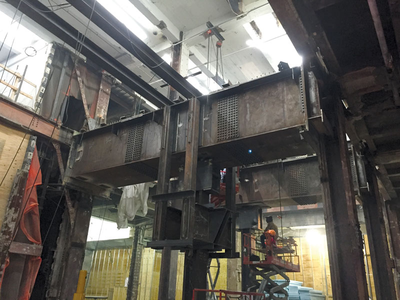
Figure 8. Jacking rig.
At 75 Rockefeller, the new girders were jacked at the existing columns to be removed. The rig shown in Figure 3 and Figure 8 was used to push the existing column up and pull the new girder down. Rivets were removed from the existing splice plates above the first floor in the column to be removed (Figure 7). To transfer the load, the axial strain in the existing columns needed to be assessed. The existing columns elongated as they were unloaded (approximately 1⁄8 inch); similarly, the reinforced columns shortened as they received additional loads (approximately 1⁄16 inch each). To achieve a separation at the splice, the columns being removed must displace by the sum of these two values relative to the columns receiving the load. This displacement was resisted by 30+ stories of the existing moment frame above. Achieving these displacements induced a stress (approximately equivalent to a 200 kip point load) into the moment frame and the new girder.
Incrementally loading the girder, and maintaining a comprehensive record of displacements and jack pressures, helped to confirm design assumptions and was invaluable for informing decisions made in the field. Each girder was loaded to the full jacking load without a visually observable separation at the column splice. Displacement records helped inform the decision on when to make the final connection.
Monitoring was continued when the jacks were released and while the column was cut. This proved important, as the channel of the final connection (Figure 3) deflected when it received load, relieving some pre-stress from the girder and resulting in an upward girder displacement of approximately 1⁄16 inch. Because of this, the column was cut with some load in it. The web of the column was removed first. The built-up flanges were then cut in a cradle starting at the toes and cutting incrementally to create a seat. The cut at one toe was started higher than the other so that they did not meet in the middle but overlapped, letting the flange of the column yield in bending as the final displacement (of just over 1⁄16 inch) occurred.
Conclusions
Altering an existing structure load path is challenging, and the manner in which it is done can significantly affect the structure. As engineers, we can produce better designs by coordinating the load transfer procedure early in the design, analyzing the effects at each stage of the procedure and carefully monitoring the behavior of the existing structure.▪
References
American Association of State Highway and Transportation Officials. 1994. AASHTO LRFD Bridge Design Specifications. Washington, D.C.
AISC. 2010. Specification for Structural Steel Buildings, American Institute of Steel Construction, Chicago.
Blodgett, O. W., & James F. Lincoln Arc Welding Foundation. 1966. Design of Welded Structures. Cleveland: James F. Lincoln Arc Welding Foundation.
W.A. Thornton, 1997, Strength and Ductility Requirements for Simple Shear Connections under Shear and Axial Load, Proceedings, AISC National Steel Construction Conference, Chicago, IL, May 7-9, pp. 37-1 through 37-17.
Project Team
Owner and General Contractor: RXR Realty
Structural Engineer: Gilsanz Murray Steficek
Architect: Kohn Penderson Fox
Steel Erector: Orange County Ironworks