
Stepping and twisting around its’ site, this “S” shaped, $25 million mountain home provides 360-degrees of scenic views. Located above Park City, Utah, the Mountain “S” Home is a structural engineering Opus. Every design element of the home represents an engineering challenge. The Mountain “S” Home was a winner of the 2016 NCSEA Excellence in Structural Engineering Awards Program, category – New Buildings under $10M.
 The architect, Wallace Cunningham, had strict requirements when it came to the structure; the structure would not interfere with the views, must fit within the curved floor plan and within the wall, roof, and eave thicknesses allotted, and would complement the architecture. It would also need to withstand heavy snow loads, large seismic forces, and the harsh mountain environment. Using materials that did not require much fabrication and that could be modified in the field would also be required, due to the short building season.
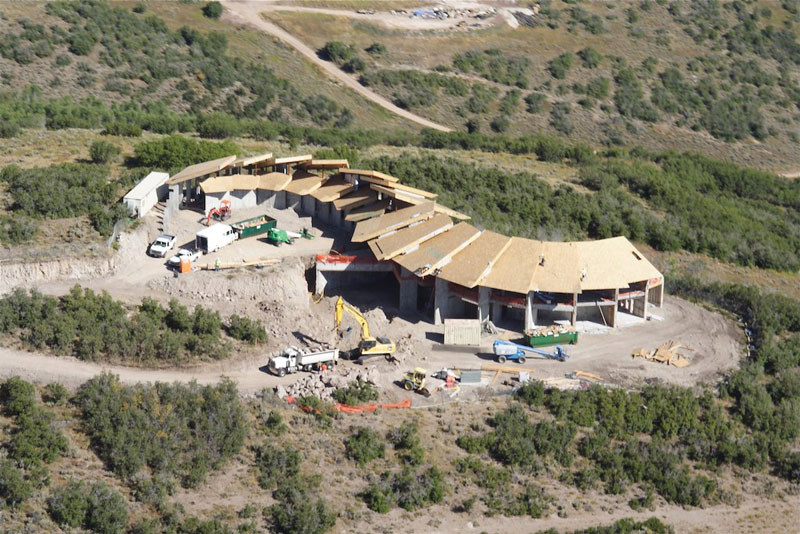
The “S” shaped home steps and twists around its’ mountain site. Although the home is curved, all of the structural members are straight.
The Mountain “S” home has 30 individual kite-shaped roofs, which, from above, resemble scales on a dragon. Each of the upper roofs appears to be supported by clerestory windows on all sides. The roofs are only 16 inches thick and cantilever horizontally as much as 21 feet while supporting 235 pounds per square foot (psf) of snow (the equivalent weight of 6 cars stacked over the entire roof). The architect insisted that the fascia not exceed 1 inch in thickness (or height) in order to have a “razors” edge, and that it not show any sign of deflection, even while supporting the 235 psf snow load plus the additional weight of snow drifting and icicles. This required transitioning from wood framing to a special stainless-steel fascia fin.
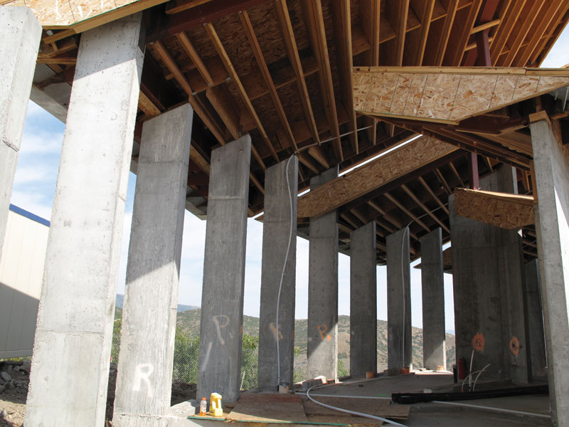
The majority of the roofs are supported by 16-foot-tall concrete piers that range from 2 feet to 8 feet in length and are only 12 inches thick. These piers not only support the heavy gravity loads but also resist the lateral loads due to wind and seismic forces, in each direction. The 16-foot-tall piers are cantilevered vertically from the structure below, which in some cases is a suspended floor, resulting in a structural irregularity. Each pier typically supports two separate roofs at two different elevations due to the stepped nature of the structure. The roofs help brace the piers in their weak direction.
The lower cantilevered roofs span perpendicular to 6-inch-thick concrete walls, resulting in tension or compression loads of 80,190 pounds on each end of each wall.
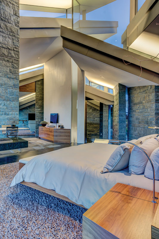
Although the building supports heavy snow loads and must resist large seismic forces, the perimeter walls are almost entirely glass. The majority of the structure’s front, back, and end walls are floor to ceiling glazing, maximizing views and providing an abundance of natural light. In many locations, you can look front to back, through the house, without any obstructions. Many of the roofs have no visible means of support. Headers were not required above the large glass openings since each roof typically spans parallel to the window glazing. Member deflection had to be limited to not over-stress the large glass openings. The wood LVL roof joists are supported at each end by steel channels, in-plane with each roof. The steel channels are welded to embedment plates that are cast into the concrete piers. Each end of the channels is typically cantilevered, some as much as 21 feet. The large cantilevers could not show any noticeable deflection, even when subjected to the significant snow load.
Foundations, suspended floors, and piers are all constructed of cast-in-place reinforced concrete, while the roofs are primarily LVL lumber with steel channels at each side. Although the floor plan is curved and stepped, all of the structural members are straight and repetitive to help minimize costs and simplify construction.
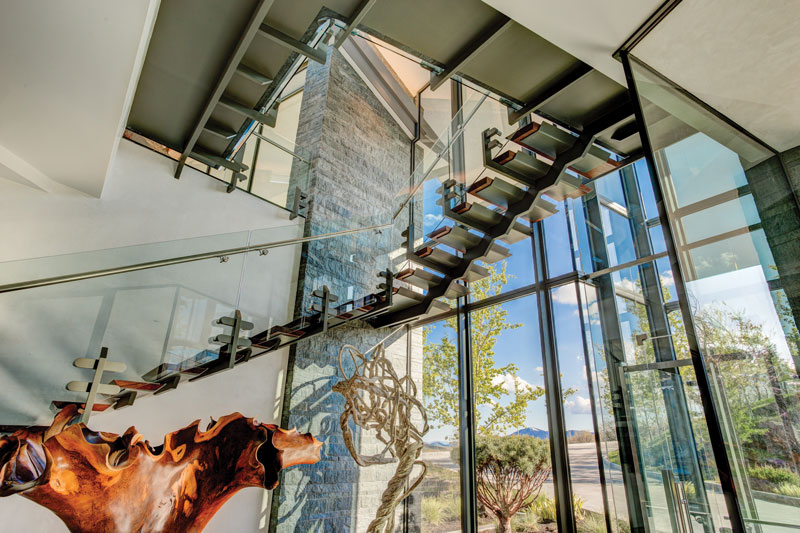
Stair treads are supported by a single “saw-tooth” stringer, cut from bar stock and then welded back together. Other treads cantilever off of a concrete wall.
The open-riser stairs are an architectural and structural design feature and focal point. The stairs have treads supported by steel plates which are supported on steel bars that are doweled into the wall and cantilever the full tread width. One of the stair runs extends past an exterior glass wall with no attachment and only one stepped-support stringer, constructed of segmented-stepped-steel bar stock welded together. There is additional plate steel around the stair opening to achieve a thin profile. Adjacent to the stairs is a glass elevator with minimal structure.
There are a couple of massive interior concrete chimneys, fireplaces, and hearths, all of which appear to float above the floor. These elements are actually cantilevered off of the ends of concrete shear walls. In addition to “floating” fireplaces, there is also a large vanity in the master bathroom that “floats” across the exterior windows.
Roofs cantilever inside and outside, with clerestory glass between. The clerestory glazing sits between two independent roof structures.
The house has a large exterior patio area that is located over the living space. There was a concern about waterproofing due to the amount of snow and severe weather in the area. The decision was to provide redundancy in the waterproofing by designing a concrete structure that would have “self-healing” cracks. The large exterior patios have a reinforcing ratio similar to that of a water tank. The increased reinforcing results in concrete that is water-tight, thus providing additional water-proofing and protection for the living space below. A membrane was also provided between the structural slab and a topping slab. Additionally, decorative water features, also constructed of reinforced concrete, were designed and reinforced for water-tightness.
In addition to the concrete piers which support most of the roofs, there are 9 staggered wall segments that range from 10 feet to 13 feet tall and are only 6 inches thick (a constraint also imposed by the architect). These thin wall segments support lower roofs which span perpendicular to the 6-inch-thick concrete segmented walls and which are staggered 2 feet, resulting in a tension or compression load of 80,000 pounds on each end of each wall. The connection required an embedment knife plate with (8) #8 dowels, 62 inches long. The 6-inch-thick pier has (10) #9 vertical bars in a 2-foot-wide jamb. This occurs in 24 locations. The 6-inch-thick segmented wall sections were required by the architect to allow for a thin stone veneer and glazing between the staggered walls. A superplasticizer was required along with several mockups and on-site testing. Initially, the architect wanted these walls to be only 4 inches thick. The engineer requested at least an 8-inch thickness but was only granted 6 inches maximum.
After several mockups, the thin walls were constructed. When the forms were removed, there were huge voids throughout the walls, which raised concern. The voids were so excessive that the walls could not be used. Concrete had to be jackhammered and removed while maintaining the reinforcing steel. The voids were the result of a superplasticizer being installed too early, and the concrete trucks taking too long to arrive at the site on a hot day. The superplasticizer had already set-off prior to the concrete even being placed in the forms. The concrete supplier took responsibility and paid for the repair and replacement of the concrete. The superplasticizer was then added to the concrete on-site, and the thin walls were successfully re-constructed.
Most of the main floor is constructed of suspended reinforced concrete slabs and beams, with a maximum span of 45 feet, allowing the lower level driveway to extend through the house. The long spanning floor system also supports wall piers which support the roof, creating structural irregularities that had to be addressed.
Multiple radial grid systems were required to lay out the structure. Although the house is curved in multiple directions, all of the structural members are straight and repetitive. Often the best structures are the ones that can be simplified, and once simplified, repeated, thus reducing costs and speeding up construction. Such was the case for this project.
This home exceeds the owners’ expectations and the expectation of all who visit it. It is one of a kind. Due to the complex nature of the structure, the local building official relied on the structural engineer for all structurally related inspections (in addition to the special inspectors).
The structure is suitable for its environment; it appears to be open, light, and airy. The home is located high in the mountains. The large exterior glass walls provide unobstructed views in all directions. All of the structural materials and members were readily available, and easy to work with. The winding hallways, tall interior walls, stepped roofs, and transom glass feels as if you are hiking through some canyon narrows as you pass through the house. Roofs cantilever inside and outside, with clerestory glass between. The clerestory glazing sits between two independent roof structures, so cantilever deflections had to be limited. With the large expanses of glass, the structure is hardly noticeable.▪