
Part 2
Part 1 of this article (STRUCTURE, October 2017) showed that if column and wall supports restrain the shortening of a post-tensioned member at stressing, part or all of the precompression intended for the post-tensioned member will be diverted to the supports. The loss of pre-compression to the supports will reduce the member’s moment capacity. This article outlines the mechanism for the development of moment capacity in fully restrained members. It also highlights the differences between members with bonded tendons and members with unbonded tendons with respect to moment capacity when subjected to support restraint. (Note: The Figure and Equation references continue the numbering from Part 1 of this series.)
Members Reinforced with Unbonded Tendons
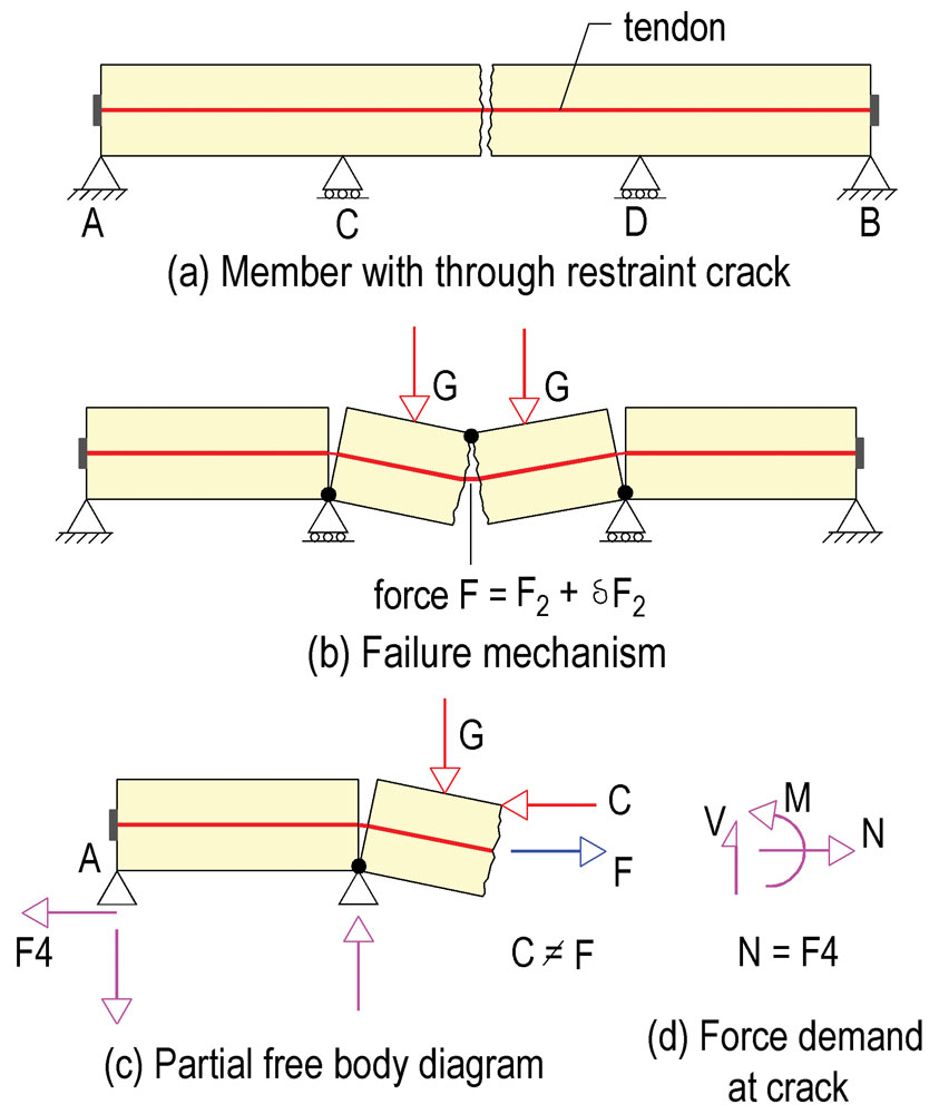
Figure 5. Failure mechanism and partial force diagram of the member with restraint crack.
Figure 5 shows a member reinforced with unbonded tendons with a single restraint crack that extends through its depth (Figure 5a). The crack resulted from shrinkage of the concrete and the restraint from the fixed end supports A and B. Supports C and D are assumed to provide no restraint, so are shown as roller supports. The tendons are shown as straight rather than profiled to simplify the presentation.
Note that, in Figure 5a, the tendon retains its force (F2) across the crack, but there is no compressive force across the face of the crack because the tendon force is diverted to the supports A and B. The force in the tendon at service (F2) is equal to the restraint force (F3), which for simplification is not shown in the figure.
An idealized free body diagram of the post-tensioning forces for the left segment of the member is shown in Figure 5c. With an increase in the applied load, the cracked sections will contact at the locations marked in Figure 5b and a compressive force C will develop at the point of contact. Also, the downward displacement of the slab before collapse will elongate the tendons, resulting in an increase (δF2) in the tendon force. The initial tendon force at the location of the crack under service condition (F2) will increase to its final value F as shown in Figure 5c. The increase in tendon force across the crack will be partially transferred to the restraining supports A and B, since the tendon strand can slide within its sheathing. At the ultimate limit state, the restraint force from the supports increases to F4 (Figure 5c).
Under service conditions, represented by Figure 5a, the force at support A is F3 and the tendon force at the crack is F2. Since the crack extends through the depth of the member, F2 = F3. In Figure 5b, the elongation of the tendon increases its force at the crack from the service condition F2 to F, as shown in Figure 5c. The external force demand at the location of the crack is the axial tension N, moment M, and shear force V, shown in Figure 5d. The axial tension N equals F4, the restraint of the support at point A at the ultimate limit state, and from equilibrium of forces along the member N = F4.
The demand actions N and M at the cracked section are resisted by the increase in tendon force across the crack resulting from the displacement of the member and the compressive force (C) developed at the newly established contact point.
The relationships are:
C = F – F4 Equation 6
M = Cz, Equation 7
M = (F–F4)z Equation 8
Where z is the lever arm between the centroids of the tension and compression forces, and F is the force in the tendon at the crack. Note that the tensile force in the tendon that contributes to the resistance capacity of the cracked section is the difference between the force in the tendon at the crack (F) and the restraint of the support (F4).
Although the presence of non-prestressed reinforcement will help to disperse the cracks and control crack width, the contribution of the non-prestressed reinforcement to moment capacity is ignored to focus on the effects of support restraint, post-tensioning, and moment capacity.
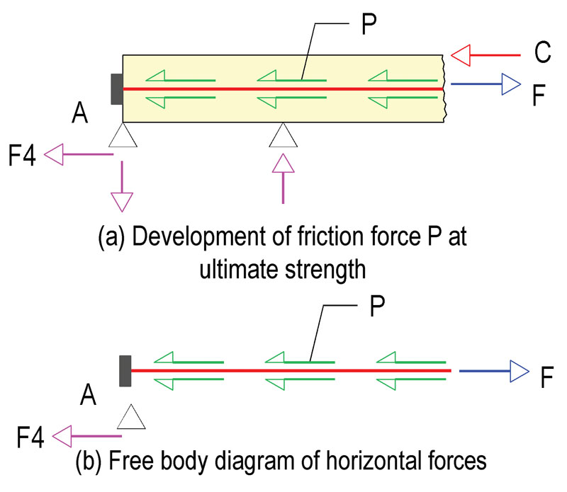
Figure 6. Development of friction force P at ultimate strength.
A free body diagram of the horizontal forces for the left segment of the member of Figure 5 is shown in Figure 6. Figure 6a shows the segment at impending collapse, where force C has developed at the contact point between the two sides of the crack. The figure shows the contribution of the friction forces (P) between a strand and its sheathing in developing the compression force (C). As shown below, the compressive force C that can develop across the crack before the collapse of the member is limited to the friction force (P) that builds up between a strand and its sheathing (Figure 6b).
From Figure 6b:
P = F–F4 Equation 9
From Figure 6a:
C = F – F4 Equation 10
Where F4 is the restraint from the support at the ultimate limit state. Therefore,
C = P Equation 11
To arrive at the upper-bound for the moment that can develop at the crack, the tendon is assumed to be stretched to rupture before failure, even though this is unrealistic for unbonded tendons.
The force F in the tendon is calculated as:
F = Aps fpu Equation 12
Where Aps is the tendon cross-sectional area, and fpu is its specified strand strength (commonly 270 ksi; 1860 MPa). In practice, fpu is unlikely to develop for unbonded tendons; this is merely a hypothetical case for an upper-bound limit. The tendon force F will decrease along the tendon length due to friction between the tendon and its sheathing. For a given tendon profile and friction coefficients, the stress loss due to friction can be readily calculated [Aalami, 2014].
Once the friction force P and hence the compressive force C across the crack are determined, the design capacity of the section is known. Note that in an actual structure, the contribution of the non-prestressed reinforcement across the crack must be included; the compressive force C will be resisted by both the tendons and the non-prestressed reinforcement. The capacity of the section depends on the location and the magnitude of the tendon force, and the location and amount of the non-prestressed reinforcement.
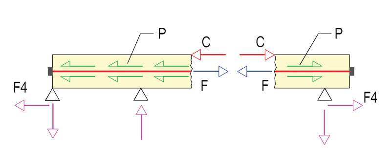
Figure 7. Partial free body diagram; non-symmetrical cracking.
In the general case, a restraint crack is likely to break the member into two non-equal lengths as illustrated in Figure 7. For static equilibrium of the member shown, the restraining forces (F4) on each side of the crack must be equal; likewise, the magnitude of the friction force (P) on each side of the crack must be the same. The friction force is a function of several factors, including the tendon length. The friction force that can be sustained across the crack will be that from the segment with the smaller force – typically the shorter side of the member. Because C = P, the moment capacity is:
M = Pz Equation 13
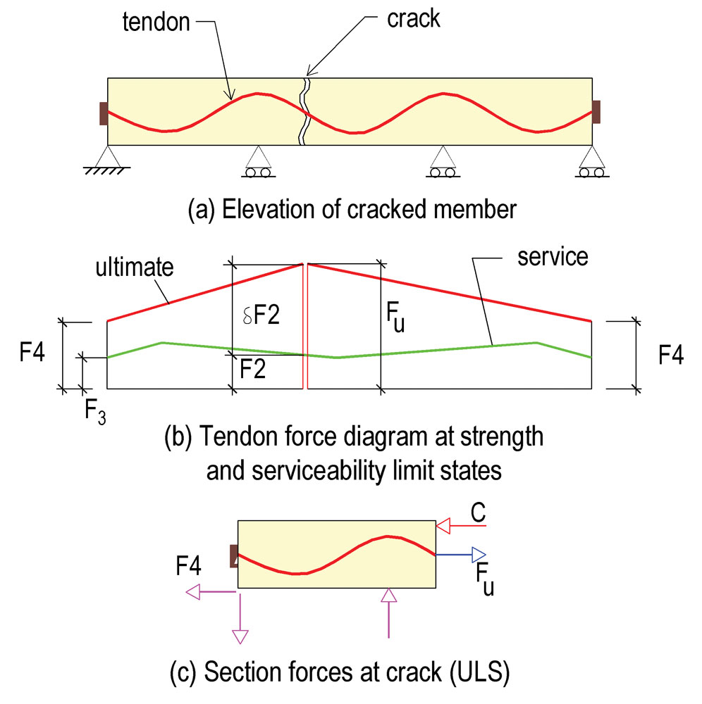
Figure 8. Service and strength limit force diagram of members reinforced with unbonded tendons.
In summary, for the conditions discussed, the maximum tensile force that is available to develop the resisting moment at the crack is limited to the friction that develops between the tendon and its sheathing at the ultimate limit state. This is further illustrated in Figure 8, where Figure 8b shows the idealized in-service and the ultimate limit state distribution of the force in the tendon. In Figure 8b, the tendon force in service, F2, at the crack location, is equal to the support restraint F3. At the ultimate limit state, the tendon force at the crack location increases to Fu.
In the preceding diagram, the force (Fu – F4) is the force that is available to resist applied moments at the ultimate limit state – the moment capacity of the section. The force (Fu – F4) is the friction force between the strand and its sheathing at the ultimate limit state.
It is concluded that when members reinforced with unbonded tendons are subject to significant support restraints, the friction between the steel strand and its sheathing plays a significant role in the strength available from the tendon at the member’s ultimate strength capacity. The larger the friction force, the greater is the available tendon strength to resist applied loads.
Members Reinforced with Bonded Tendons
Members reinforced with bonded tendons will develop a larger moment capacity at restraint cracks than members that are reinforced with the same amount of unbonded post-tensioning. There are three reasons for this.
First, bonded tendons typically develop their specified strength (fpu) before failure, whereas members reinforced with unbonded tendons tend to undergo large deflections and reach failure due to crushing of concrete or excessive deflection before the tendons can reach their specified strength. Consequently, the American Concrete Institute’s ACI 318 and Euro Code 2 (EC2) specify a significantly lower permissible stress (fps) for unbonded tendons when calculating flexural capacity. ACI 318 limits the increase in tendon stress at ultimate strength for unbonded tendons to between 30 to 60 ksi (206 to 413 MPa), depending on the span to depth ratio. In EC2, the increase is limited to just 100 MPa (15 ksi). This is only a 7 to 9% gain in strength over service conditions, leaving about 30% of a tendon’s strength unused at member failure.
Second, for members with bonded tendons, the increase in demand moment at a point results in an increase in the tendon force at that location. The local increase in tendon force is not offset by support restraint like it is for unbonded tendons.
Third, the fact that the friction between the strand and the duct during stressing of a bonded tendon is higher than the friction between the strand and the sheathing of an unbonded tendon is advantageous at the strength limit state of a cracked section.
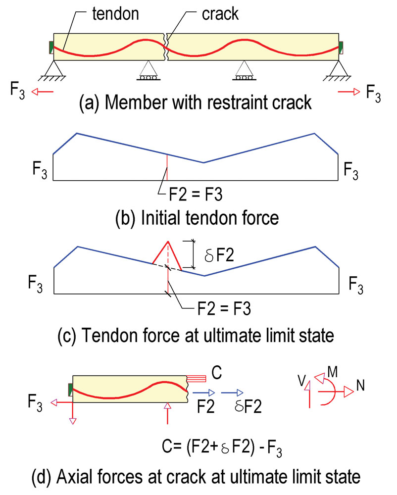
Figure 9. Forces at ultimate limit state in a member with bonded tendon and restraint cracking.
Consider the member with a bonded tendon shown in Figure 9. Let the restraint from the supports be large enough to cause the cracking shown in Figure 9a. The force in the tendon at grouting follows the friction diagram shown in Figure 9b. Let the force in the tendon at the crack location under service conditions be F2. For static equilibrium, F2 must be equal to the restraint of the support (F3) while the gap at the crack is open. An increase in the applied moment at the crack location will tend to elongate the tendon locally, leading to an increase in the tendon force by δF2 (Figure 9c).
The demand actions at the crack location (Figure 9d) are moment M, axial force N, and shear V. From equilibrium of the forces, N is equal to F3, the force due to restraint of the support.
The tensile force available to resist the demand actions at the crack location is:
T = F2 + δF2 – F3 Equation 14
Since at the crack location F2 = F3, the available force (T) to resist the induced moment is equal to δF2.
Likewise, from equilibrium of forces, the compression force C is
C = (F2 + δF2) – F3 = δF2 Equation 15
The moment, M, that can be developed at the crack is equal to:
M = Cz = δF2 z Equation 16
Comparison between Unbonded and Bonded Systems
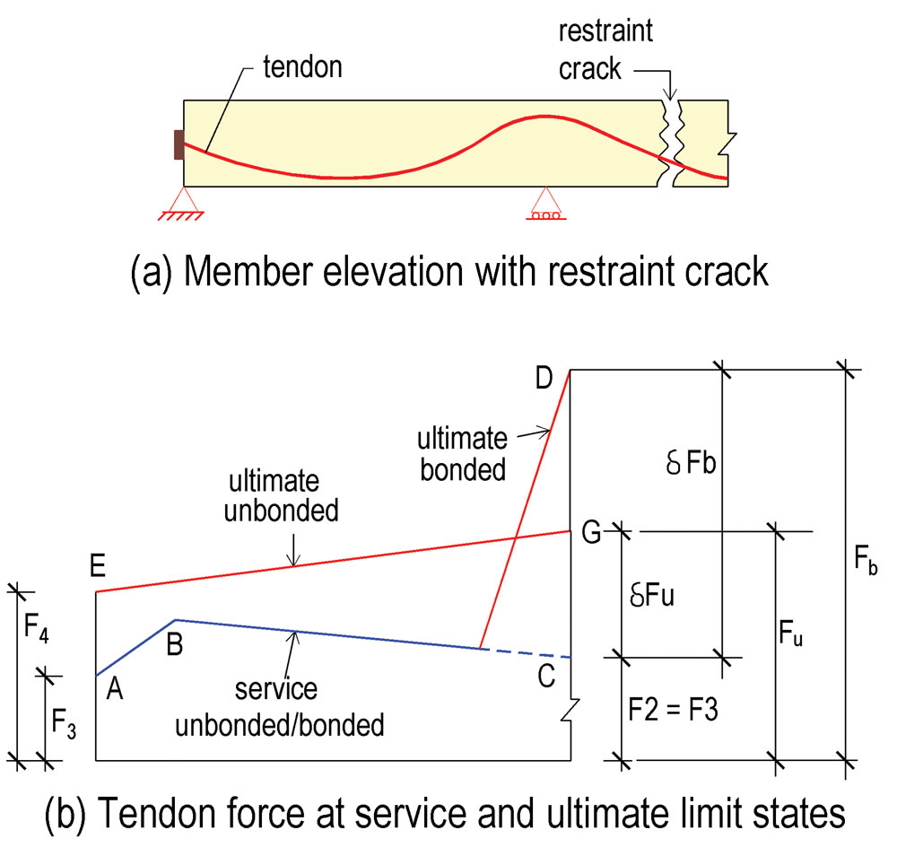
Figure 10. Comparison of tendon force at service and ultimate limit (strength) states for bonded and unbonded post-tensioning tendons.
Figure 10 compares the effect of restraint cracking on the strength of a member with unbonded tendons to that of a member with bonded tendons. The diagram shows the distribution of force in the tendon for the segment to the left of the crack. Line ABC is the force in the tendon at service conditions. The force is influenced by the friction between the tendon and its sheathing, or duct and the seating loss at stressing; to simplify the presentation, the force is assumed to be the same for bonded and unbonded systems at service conditions. For a bonded system, the ultimate moment at the crack location will include a local increase in the tendon force as shown by Point D (stress Fb). The tendon force available to resist the demand moment is equal to the local increase in the tendon force (δFb) shown by CD. For an unbonded tendon, the distribution of force at the strength limit is governed by the re-alignment of the friction force along the tendon length from line ABC to line EG. The force available to resist the moment demand is (F2 + δFu) – F4 = Fu – F4.
Hence, the net force (T ) from the post-tensioning tendons available to resist the demand moment at the crack is:
Unbonded: T = Fu – F4 Equation 17
Bonded: T = Fb – F3 = δFb Equation 18
Conclusion
This article explains the reduction in moment capacity of post-tensioned members due to the loss of precompression when restraint from wall and column supports prevents free shortening of the members during stressing. It concludes that the contribution of tensile force from prestressing tendons to the moment capacity of a post-tensioned member is tied to the value of precompression from post-tensioning. If the supports prevent all shortening, the entire post-tensioning force will be diverted to the supports, leaving the member with no precompression – hence, there is no contribution from post-tensioning to moment capacity.
The article highlights the importance of detailing at the lowest levels of building structures, where the constraint of the supports is most pronounced. The addition of non-prestressed reinforcement helps to disperse the cracking and control the crack width but does not compensate for the loss in moment capacity caused by support restraint. The added non-prestressed reinforcement must not be less than the loss of contribution to moment capacity from post-tensioning due to support restraint.
The article also explains why the effect of support restraint is not the same for members reinforced with unbonded tendons and members reinforced with bonded tendons. It concludes that the loss of moment capacity due to support restraint is significantly greater for members with unbonded tendons than for members with bonded tendons.▪
References
Aalami, B. O., Post-Tensioned Buildings; Design and Construction, www.adaptsoft.com, PT-Structures.com, Redwood City, CA, Mar 2014, 450 pp.
ACI 318-14, (2014), Building Code Requirements for Structural Concrete (ACI 318-14) and Commentary, American Concrete Institute, Farmington Hill, MI 48331, www.material.org, 503 pp.
EC2 – 1992-1-1:2004, (2004), Eurocode 2: Design of Concrete Structures, Part 1-1: General rules and rules for buildings, European Committee for Standardization, CEN, Brussels.