
Flat plate voided concrete slab systems have been used for many years in Europe and other parts of the world. These systems are becoming increasingly popular in the U.S. This is due to many inherent benefits which include reduced self-weight (resulting in smaller column sizes and foundations as well as smaller seismic forces); larger allowable superimposed loads for given span lengths; economical longer spans; reduced floor-to-floor heights; and accelerated construction schedules.
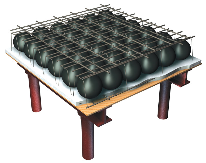
Figure 1. Flat plate voided concrete slab system.
Contemporary systems, pioneered by BubbleDeck® and Cobiax®, utilize hollow, plastic balls (commonly referred to as void formers) made of high-density, recycled polyethylene (HDPE) that are regularly spaced within the overall thickness of the concrete slab. Void formers are usually spherical or ellipsoidal and are positioned within wire support cages to create modular grids (cage modules), which are locked between the upper and lower reinforcement layers in the concrete slab (Figure 1). Mild reinforcing bars are commonly used as the primary flexural reinforcement in the slab. Once the top layer of concrete is cast over the cage modules, a two-way slab system of uniform thickness is created.
Flat plate voided concrete slab systems are designed and detailed in accordance with Building Code Requirements for Structural Concrete (ACI 318) just like any other two-way slab system. It is important to note that the void formers do not contribute to the nominal flexural and shear strengths of the slab system; their only role is to provide voids in the slab. More information on these systems can be found in CRSI publications, Design Guide for Voided Concrete Slabs and Frequently Asked Questions (FAQ) About Flat Plate Voided Concrete Slab Systems.
Fire Resistance
Numerous fire tests have been performed on BubbleDeck systems and Cobiax systems in accordance with the provisions in Fire Behavior of Building Materials and Building Components; Building Components; Definitions, Requirements, and Tests (DIN 4102-02). Fire-resistance ratings of at least 2 hours were obtained from these tests for flat plate voided concrete slabs with a cover of ¾-inch to the main flexural reinforcing bars. The time-temperature curve used to test assemblies in the DIN requirements is essentially the same as that prescribed in Fire-resistance Tests – Elements of Building Construction – Part 1: General Requirements (ISO 834). ISO 834 and ASTM E119 time-temperature curves are also essentially the same, and it has been shown that the differences in severity between the two tests are negligible. Therefore, it follows that the results obtained from assemblies tested by the DIN requirements would be the same as those that would be obtained if the assemblies were tested in accordance with ASTM E119 requirements.
A fire test to supplement those performed previously was conducted in June of 2017 at the Fire Testing Laboratory of NGC Testing Services in Buffalo, NY. Information on the test assembly and methods, and a summary of the results, are presented below.
Test Assembly
The test assembly consisted of an 8-inch thick concrete slab that was14 feet by 18 feet (the plan dimensions were limited by the size of the furnace test frame). The slab contained 4-inch-thick ellipsoidal void formers with a diameter of 123⁄8 inches that were spaced 13¾ inches on-center within the cage modules. A total of 140 void formers were used in the slab.
Normal-weight concrete with siliceous aggregate and a design compressive strength of 5,000 psi was specified. Slab reinforcement consisted of ASTM A615 Grade 60 #4 bars spaced 12 inches on-center in both primary directions at the top and bottom of the slab with a ¾-inch clear cover. The cage modules were tied to these reinforcing bars, and a 13-inch-wide strip of solid concrete was provided around the perimeter of the slab. Construction of the assembly followed typical construction procedures used in the field for these types of systems. The layout of the void formers in the slab before casting of the concrete is shown in Figure 2.
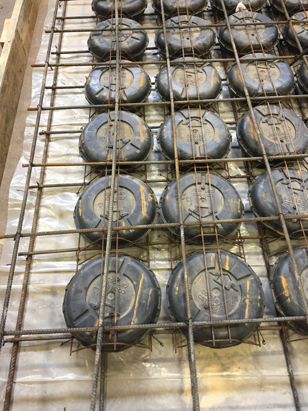
Figure 2. Layout of void formers in test assembly
The slab was cured for 28 days prior to testing, and its moisture content was measured to be 69% on the day it was tested.
An 8-inch-thick slab was tested because that is the minimum slab thickness that can be specified for this type of system given the current product lines available. Because of savings in self-weight, long spans (and slabs thicker than 8 inches) are typical. For example, a 15.5-inch-thick slab can easily span 40 feet and longer for residential and office loading. Applying the fire rating obtained from the 8-inch assembly to commonly used thicker slabs is conservative.
Method
The assembly was tested in accordance with the requirements of ASTM E119. The furnace combustion chamber was fitted with 80 uniformly located natural gas burners, which provided an even heat flux across the assembly’s exposed surface. Furnace temperatures were maintained in accordance with the ASTM E119 time-temperature curve and were measured and recorded at 15-second intervals. The surface temperature of the unexposed surface was measured and recorded at 15-second intervals as well using 9 thermocouples located in accordance with ASTM E119 requirements.
The edges of the slab on all 4 sides were supported vertically by the test frame; no restraint was provided for thermal expansion or rotation. As such, the assembly was unrestrained during the duration of the fire test, which is usually conservative for cast-in-place concrete slab systems.
The assembly was loaded during the entire time of the test with a uniformly distributed load of 80 psf using water-filled steel tanks. This load meets the ASTM E119 load requirement for floor and roof systems: “Throughout the fire-resistance test, apply a superimposed load to the test specimen to simulate a maximum-load condition. This load shall be the maximum-load condition allowed under nationally recognized structural design criteria unless limited design criteria are specified, and a corresponding reduced load is applied.”
The vertical deflection of the assembly was measured throughout the test with 3 plumb bobs located at the center and quarter points of the slab.
Results
A few minutes into the fire test, sporadic spalling of concrete occurred beneath the void formers. Some of the void formers melted and dripped on to the furnace chamber floor while others remained mostly intact. At approximately 30 minutes into the test, spalling decreased significantly as did the rate of vertical deflection of the assembly.
At 2 hours into the test, none of the ASTM E119 conditions to terminate testing were met. At 2 hours and 52 minutes, the test was terminated because the temperature recorded at one of the thermocouples at the unexposed surface exceeded the ASTM E119 individual limiting temperature rise of 325 degrees Fahrenheit. The maximum deflection was approximately 3.5 inches at that time. Throughout the duration of the test, the assembly supported the applied loading with no signs of collapse.
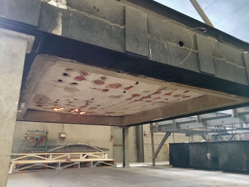
Figure 3. The underside of test assembly after fire testing.
The underside of the assembly after the fire test is shown in Figure 3. Although the concrete had spalled at various locations, the exposed reinforcing bars exhibited minor to no damage due to the fire.
Equivalent Slab Thickness and Fire Rating
Table 722.2.2.1 of the International Building Code (IBC) provides minimum slab thickness of reinforced concrete floor and roof assemblies to achieve fire-resistance ratings based on aggregate type. Flat plate voided concrete slab systems are similar to slabs with ribbed or undulating soffits, so an equivalent slab thickness must be calculated for use in Table 722.2.2.1.
In general, the equivalent thickness of a flat plate voided concrete system is equal to the net volume of concrete divided by the floor area. The net volume of concrete is equal to the volume of concrete of a solid slab minus the average concrete displaced by the void formers:
Volume of solid 8-inch slab = 8/12 = 0.67 cu ft/sq ft
For the void formers used in the test assembly, average concrete displaced = 0.18 cu ft/sq ft
Net volume of concrete = 0.67 – 0.18 = 0.49 cu ft/sq ft
Thus, the equivalent thickness of the test assembly = 0.49 ft = 5.9 inches
An equivalent thickness of 5.9 inches corresponds to a 2-hour fire-resistance rating for a normal-weight concrete mix with siliceous aggregate (according to Table 722.2.2.1, a 5-inch thickness is required for a 2-hour rating, and a 6.2-inch thickness is required for a 3-hour rating). The fire rating based on equivalent thickness is essentially the same as that determined from the fire test.
Conclusion
Based on the results from the fire test, it can be concluded that the flat plate voided concrete assembly, constructed of the materials and in the manner described previously, achieved a 2-hour unrestrained assembly rating when exposed to fire in accordance with the test method prescribed in ASTM E119. This test confirms the appropriateness of the application of Appendix X3 of ASTM E119 and Section 703.3 of the International Building Code (ICC 2015) for flat plate voided concrete slabs.
This fire rating is conservative because, in actual structures, cast-in-place reinforced concrete floor and roof slabs subjected to fire are usually restrained by adjoining monolithic slabs and vertical elements. Table X3.1 in Appendix X3 of ASTM E119 provides guidance for determining restrained and unrestrained conditions of construction. According to that table, all types of concrete cast-in-place floor or roof construction, where the floor or roof construction is cast with the framing members, are considered to be restrained with respect to effects of thermal expansion.
No signs of structural collapse of the assembly were evident at any time during testing. The testing was terminated because of the amount of heat transmission through the slab. Thus, at least a 2-hour fire-resistance rating can be achieved for thicker flat plate voided concrete slabs.▪
References
ACI (American Concrete Institute). 2014. “Building Code Requirements for Structural Concrete and Commentary.” ACI 318-14, Farmington Hills, Michigan.
ASTM (American Society for Testing and Materials). 2016. “Standard Test Method for Fire Tests of Building Construction and Materials.” ASTM E119 – 16, West Conshohocken, Pennsylvania.
CRSI (Concrete Reinforcing Steel Institute). 2014. Design Guide for Voided Concrete Slabs. Schaumburg, IL.
CRSI (Concrete Reinforcing Steel Institute). 2017. Frequently Asked Questions (FAQ) About Flat Plate Voided Concrete Slab Systems. Schaumburg, IL.
DIN (Deutsches Institut für Normung). 1977. “Fire Behavior of Building Materials and Building Components; Building Components; Definitions, Requirements and Tests.” DIN 4102-2, German Institute for Standardization, Berlin, Germany.
ICC (International Code Council). 2015. International Building Code. Washington, D.C.
ISO (International Organization for Standardization). 1999 (Amended 2012). Fire-resistance Tests – Elements of Building Construction–Part 1: General Requirements. ISO 834-1.