
This is the type of project that gives geotechnical, geostructural, and structural engineers goosebumps – in a good way. VCU Health’s vision for a new Children’s Hospital of Richmond at VCU Children’s Pavilion required designing in the fourth dimension, where the past, present, and future of the physical facilities critical to this ambitious undertaking were simultaneously considered. Goals were lofty. Not only would it become the largest and most advanced outpatient facility dedicated to children in the region, but the reimagined pavilion was also expected to serve as a gateway to Virginia Commonwealth University’s urban medical campus in downtown Richmond. And that was just for starters.
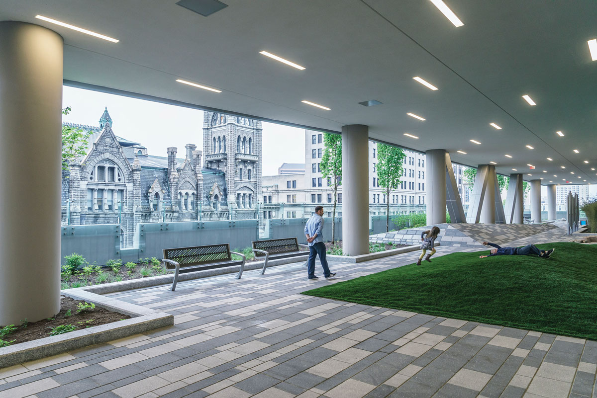
The Sky Lobby garden is perhaps one of the most inviting features to families seeking pediatric medical care at this facility. Courtesy of Michael Stavaridis.
On the surface, the program directive to the design team, led by HKS Architects, Inc., was clear and concise. With an all-in budget of $200 million, on a site adjacent and practically connected to the existing Children’s Pavilion, design and construct a 640,000-square-foot, 15-story building rising 11 floors above grade and descending four stories below it. The design had to incorporate structural systems that would allow for seven floors of future vertical expansion and also extend the below-grade levels to the north, occupying the entire block. Last but not least, although the plan required demolition of a portion of the existing pavilion, it had to remain open and operational during construction.
Together, these factors formed an irresistible challenge for two local engineering firms to surmount. As part of the HKS team, structural engineer Dunbar Milby Williams Pittman & Vaughan (DMWPV) and geotechnical/geostructural engineer Schnabel Engineering were charged with designing the support of excavation, the structural support and underpinning of the existing pavilion, and structural support of the new building.
Location, Location, Location
Previously a surface parking lot, the project site occupies less than an acre and is bounded by busy East Broad Street, and North 10th and 11th Streets. With the adjacent pediatric pavilion already in place, VCU saw the expansion as a means to enhance their brand and re-energize the neighborhood and campus gateway while consolidating services from various locations under one roof to better serve the community. The new Pavilion at 1000 E. Broad Street is on a GRTC Transit System bus route and features a 600-space attached parking garage.
Diving into a Deep Excavation
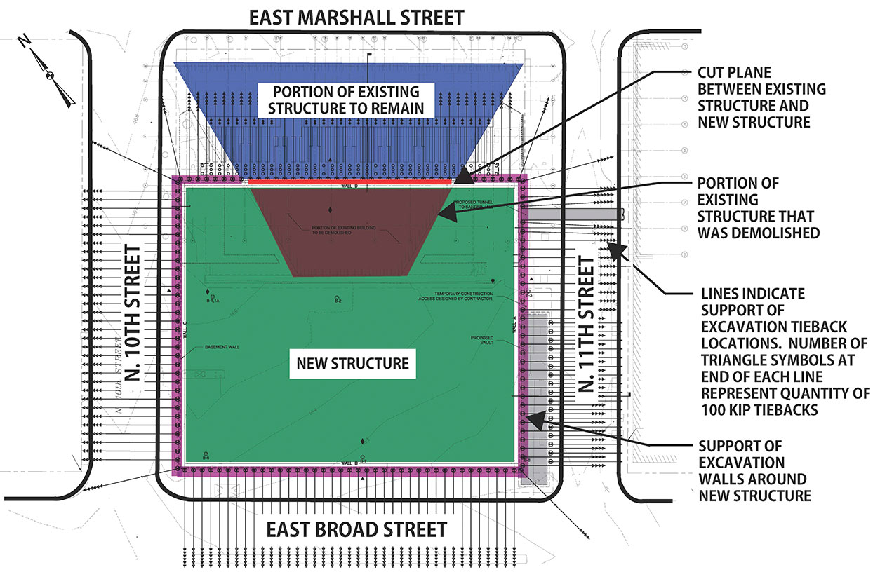
Site location and position of the new building relative to the existing pediatric care building.
Extensive subsurface exploration – 23 test borings, a cone penetrometer test, three pressuremeter tests, and strength and consolidation testing on Shelby tube samples – confirmed the site geology to be typical of downtown Richmond. The good news was that the Miocene clay and silt soils were heavily pre-consolidated and suitable for support of heavy building loads.
The real challenge lay in the fact that the excavation for the new Pavilion extended 55 feet below street level, which is 35 feet below the foundations of the existing pediatric care facility. This prompted creative thinking and serious teamwork on the part of DMWPV and Schnabel to address two pivotal issues: excavation support and existing building support.
Excavation Support
A permanently tied-back soldier pile and lagging support of excavation (SOE) system was selected based on consideration of the subsurface conditions, and site and design constraints. The system can resist the lateral earth pressures instead of relying on the building framing and facilitates future expansion to the north. Schnabel performed the initial SOE design, which was subsequently optimized by design-builder Nicholson Construction. The system consisted of 143 drilled and set piles and 472 tiebacks and was designed to limit horizontal and vertical deflection of the adjacent building to one inch.
Existing Building Support
The excavation below and adjacent to the pediatric care facility at the demolition cut plane necessitated supporting the existing shallow foundations. Because the two structures were to remain independent, neither gravity nor lateral loads from the existing building could be transmitted to the new one.
Gravity loads at the cut plane were supported on a 10-foot, 8-inch wide by 3-foot, 6-inch deep concrete underpinning-style grade beam along the entire length of the cut plane. The underpinning grade beam was supported on 95 vertical micropiles designed to transfer gravity forces from the structure to below the bottom of the SOE. The micropiles were typically installed in groups of three and spaced at 6 feet on-center. The installation took place in the building’s lowest parking level under headroom conditions of nine feet or less. The vertical micropiles were each designed for a service level compression load of 96 kips, bonded in the Miocene stratum, and were a total length of 52 feet.
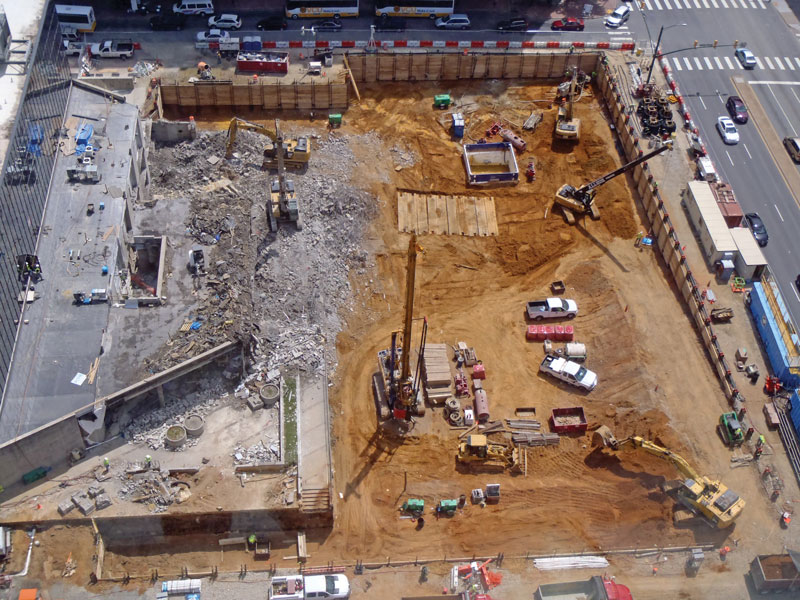
Partial demolition of the existing VCU Children’s Pavilion. New SOE/underpinning to be installed below remaining three-story portion.
Demolition of a portion of the pediatric care facility, and excavation adjacent to it, also required the design of new lateral support systems to compensate for unbalanced lateral earth pressure and to keep the building from moving toward the excavation.
The structure to remain in place after demolition was modeled using Autodesk Revit and Bentley RAM Elements finite element analysis software. Multiple options to support the lateral loads on the structure and transfer approximately 2,300 kips of service level lateral load to the soils below were considered; internal buttresses and shear walls was the option of choice. The buttresses consist of seven 9-foot by 6.75-foot, full-height concrete columns spaced at 24 feet on-center along the cut plane, each with an integral 2-foot-thick concrete shear wall perpendicular to the line of excavation. The continuous underpinning grade beam at the cut plane connects the buttresses and is supported by the system of vertical micropiles detailed above. The groups of micropiles are centered between the SOE tiebacks.
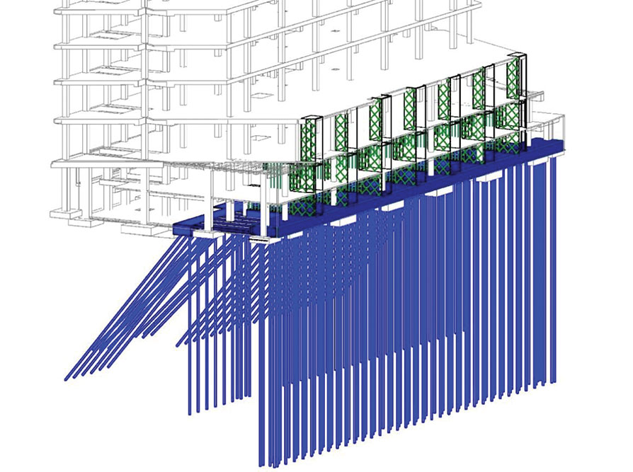
Schematic of the system of underpinning and bracing below the existing pediatric care building.
To resist the lateral forces and prevent the building from moving towards the excavation, an A-frame system of post-tensioned battered piles coupled with vertical micropiles was constructed 30 feet away from the building cut plane, in line with the vertical micropiles along the front grade beam, to avoid the SOE tiebacks. Horizontal tie beams consisting of post-tensioned tie rods were used to transfer the lateral loads from the grade beam at the cut plane back to the line of the A-frame micropiles. Thirty-four coupled battered pile assemblies connected to 30 horizontal tie beams containing a total of 60 horizontal post-tensioned tie rods were constructed.
A sophisticated instrumentation and monitoring system provided real-time data that was used to verify the performance of the SOE and underpinning. The total horizontal movement of the existing building during the monitoring period was approximately 0.4 inches.
New Building Structural Elements
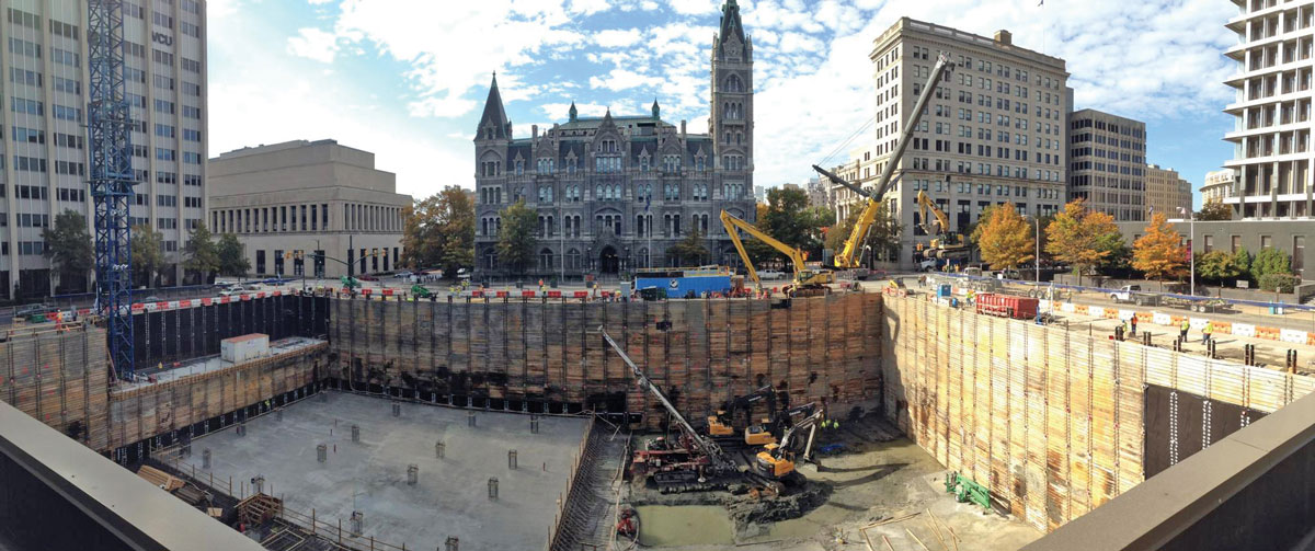
Taken from the pediatric care building, excavation, and SOE at the start of mat foundation construction. Historic Old City Hall is in the background. Courtesy of Skanska USA.
The new building is supported on a mat foundation on Miocene soils. Typical mat thickness is 6 feet with 5,000 psi compressive strength concrete, which eliminated the need for shear reinforcing where the columns bear on it. The contractor developed a detailed mass concrete plan that addressed logistics and thermal control during curing. The specifications limited maximum internal temperature of the concrete to 160°F to avoid damage by delayed ettringite formation. A maximum temperature differential of 35°F was stipulated to mitigate cracking of the concrete due to thermal stresses. The concrete supplier chose to use mix designs with 60 percent slag cement to assist with meeting thermal control limitations. The mat was poured in four quadrants totaling 1,100 cubic yards.
The four floors below and four levels above grade were constructed from CIP concrete. For reasons of future flexibility while making building modifications, VCU Health requested a non-post-tensioned design so 12-inch-thick two-way slabs spanned the typical 30-foot by 30-foot bays without the need for any drop panels or slab shear reinforcing in most cases. Measures taken to push deck repair projects many decades into the future included dosing parking level slabs with three gallons/cubic yard of calcium nitrite corrosion inhibitor; a 2-inch concrete cover over top reinforcing bars; maintaining a low water/cement ratio between 0.39 and 0.42; and limiting chloride ion penetrability to 1,000 coulombs in 28 days per ASTM C1202. Typical gravity columns were 36 inches by 36 inches using 8,000 psi compressive strength concrete at the lower levels. ASTM A615 Grade 65 KSI reinforcing steel was used in the columns to assist with rebar congestion at beam intersections and column splices.
The six outpatient floors plus mechanical penthouse were constructed to accommodate the addition of another seven levels above. Typical floor slab construction consisted of 3.5 inches of lightweight concrete over a 2-inch composite deck for a two-hour fire rating. While typical 30-foot by 30-foot bays of all clinical levels were framed with W16 beams and W24 girders, the first steel level above the concrete framing had beams as deep as W33 connecting into W36 girders in order to meet vibration requirements for sensitive imaging equipment.
Steel-braced frames in the upper levels align atop CIP concrete shear walls of the parking levels to provide lateral force resistance. A Seismic Response Modification Coefficient (R) value of 3.0 was used to avoid prescriptive joint design requirements of AISC 341. Wind loads for this structure were close in value to seismic forces so there was little to gain by using a larger R-value.
The Sky Lobby is constructed on the uppermost level of CIP concrete framing. This portion of concrete framing is depressed several feet to accommodate the depth of planters and allow for the structural slabs to slope to drains. The floor system was designed for heavy concentrated loads of landscaping boulders, as well as a 20,000-pound allowance for mature trees in each planting well.
Conclusion
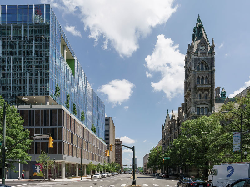
The completed Pavilion stands at the northwest corner of East Broad Street and North 11th Street in Downtown Richmond, Virginia. Courtesy of Michael Stavaridis.
In the second decade of the 21st century, few projects have as much social resonance as those connected with health care and those connected with children. This one exemplifies the best of both. The new Children’s Pavilion opened on March 21, 2016, to the kind of enthusiasm one might expect when outpatient pediatric services expand from a 54,000-square-foot facility well past its prime to a gleaming high-tech tower housing clinics, radiology, same-day surgery, lab testing, dialysis, infusions, family amenities and more, in an environment custom-tailored for kids.
Even before construction was finished, the Pavilion had been recognized for its innovative design. Awards include the 2013 Honor Award of Excellence in Architecture (AIA Richmond Chapter), 2014 National Healthcare Design Award (AIA Academy of Architecture for Health), 2015 Future Healthy Built Environment Award (Design & Health International), and 2015 Concrete Excellence Award (American Concrete Institute Virginia Chapter).
By the time it was completed after five years of planning and preparation, compiled data spoke volumes about the scope of this undertaking: $200 million invested, 2,450 tons of steel, 523,000 pounds of sheet metal, 41,000 cubic yards of concrete, seven floors of structured parking, and 83 new exam rooms.
Now, after more than a year in operation, the building has become a downtown Richmond landmark, revitalizing the historic and vital Broad Street corridor as it has improved the lives of many children and their families. After all, that is something worthy of support.▪
Project Team
Owner: VCU Health, Richmond, VA
Structural Engineer: Dunbar Milby Williams Pittman & Vaughan (DMWPV), Richmond, VA
Architect: HKS, Inc., Richmond, VA
Program Manager: JLL, Richmond, VA
Geotechnical/Geostructural Engineer: Schnabel Engineering, Glen Allen, VA and West Chester, PA
Construction Manager: Skanska USA, Richmond, VA
Specialty Geotechnical Contractor/Designer: Nicholson Construction Company, Canonsburg, PA
Concrete Subcontractor: Cleveland Cement Contractors, Inc., Colonial Heights, VA
Structural Steel Fabricator: SteelFab, Inc., Emporia, VA
Structural Steel Erector: W. O. Grubb, Richmond, VA
Earthwork Subcontractor: C.T. Purcell, Inc., Montpelier, VA
Concrete Suppliers: Vulcan Materials Company, Richmond, VA and S.B. Cox Ready-Mix, Inc., Rockville, VA