
Currently under construction in Vancouver, Washington, Waterfront Park is part of a 32-acre mixed-use urban redevelopment project on a site that is being reclaimed, having previously been used as a paper mill. Developed by the City of Vancouver, the 7.3-acre Waterfront Park features open lawns, picnic areas, viewpoints, and shoreline paths along nearly 2,500 feet of Columbia River waterfront. When completed in the Spring of 2018, the Grant Street Pier will become the focal point of the new park.
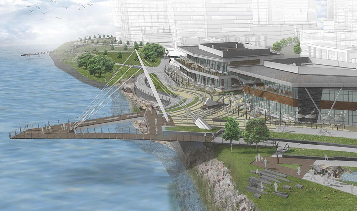
Grand Street Pier rendering.
The Grant Street Pier is a concrete, cable-stayed structure projecting almost 110 feet over the Columbia River. The 2½-inch diameter steel cables are anchored at the end of the pier and at two concrete back-stays. They are supported at the center by a 75-foot-tall steel pipe mast. The pier deck is three-foot-thick post-tensioned concrete that tapers to only six inches thick at the outside edges. A concrete abutment supports the pier deck, the mast, and one of the two backstays. The second mast backstay is anchored into an independent mat footing supported on 11 micropiles. Sliding of the backstay anchor footing is restrained by three grade-beams attached to the abutment slab.
The concrete abutment wall is two feet thick at the base and tapers up to six-and-a-half feet thick at the top. The wall taper was a desired aesthetic for the pier base just above the waterline. Seven 18-inch-thick counterfort walls, orthogonal to the abutment wall, anchor the pier slab to the mat foundation. The mat foundation is a six-foot-thick concrete slab supported by twenty-seven five-foot-diameter drilled shafts.
Serious problems developed during the construction of the drilled piers, resulting in extensive and expensive repairs.
Foundation Design
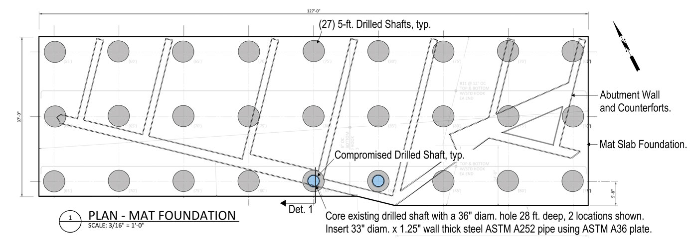
Structural components of foundation abutment.
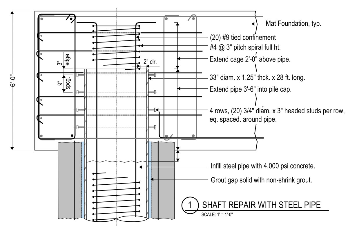
Altered structural conditions at the top of the concrete-filled steel pipe repair.
The overall abutment foundation layout was highly constrained by the site – the Columbia River on the south edge, a property line boundary to the north, and a large sewer pipe that runs through the center of the footprint that could not be realigned for this project. One requirement of the permit was that the foundation could not be located waterward of the biological ordinary-high-water mark (OHWM). Thus, the alignment of the OHWM dictated that the foundation orientation be non-perpendicular to the primary axis of the pier span over the water. This resulted in a skewed axis of the mat slab foundation and drilled shafts relative to the main axis of the abutment walls and pier, resulting in a substantial torsion on the foundation mat slab in addition to the expected flexure and shear.
The underlying soil consisted of 25 feet of loose fill over ten feet of sand and then gravel and cobbles to depth. The loose fill contained sand, organics, some silt, wood debris, and large pieces of concrete debris. The concrete debris was not discovered by the geotechnical borings. The fill material and sand are subject to liquefaction during a seismic event. Because of the topography of the underlying gravels and the riverbank, these materials are also subject to lateral spread toward the river, with an estimated lateral spread of up to 15 feet.
Because the excavation for the foundation was below the river level, a sheet pile cofferdam was needed to facilitate the pier foundation construction. The portion of the cofferdam that encroached on the OHWM was required to be removed; however, the landside portion of the cofferdam could remain. It was decided to utilize this portion of the cofferdam to resist demands due to liquefaction. As such, 36 tieback anchors were needed along the back face of the sheet pile cofferdam to resisting the primary demand of lateral spread. The tops of the sheet piles were cut off five feet below grade; since this was below the top of the pier slab, the abutment and drilled shafts were required to resist the portion of liquefaction demand not supported by the sheet pile wall.
The bottom of the mat slab foundation is 14 feet below the OHWM and approximately 15 feet above the gravel and cobble layer. The result is that 15 feet of soil below the mat foundation has the potential to liquefy due to a seismic event. This resulted in the drilled piers being designed as cantilever elements when subject to seismic demands. The seismic overturning, when combined with the overturning of the cantilever pier, created axial loads of almost 2,000-kips compression and bending moments of 45,000 kip-ft in the forward most drilled shafts, and tension loads of 610-kips and bending moments of 42,000 kip-ft in the rearmost drilled shafts based on allowable load combinations. These demands and the geotechnical conditions required drilled shafts with up to 70 feet of embedment into the gravel, resulting in a total shaft length of 90 feet.
Construction
The shafts were installed with oscillating sectional casing using a Bauer BG40 track-mounted drill rig. Material inside of the casing was excavated using a digging bucket, a cleanout bucket, a flight auger, and a rock auger depending on the material encountered. During the drilling process, a water head was maintained above the river elevation to prevent heaving.
After the shafts were drilled and cleaned, the reinforcing cage was lowered into the shaft and concrete was placed using a tremie pipe. As the concrete level rose, the casing was retracted.
The drilling occurred from a bench elevation 10 feet above the top of the drilled pier. The contractor excavated for the cofferdam tremie seal and mat foundation after the drilled shafts were installed. This difference in elevation was taken up by a weak concrete mixture that could easily be chipped away from the shaft dowels once the excavation for the mat slab was complete. During the retraction of the casing of the two final shafts, some construction problems were encountered. The issues for both shafts were similar – as the last segments of casing were withdrawn, the top of concrete fell about 2.5 feet below the bottom of the top collar leaving a portion of shaft uncased. The soil around the top collar settled as the contractor continued to place concrete in the shaft. One shaft took 14 more yards of concrete than the estimated shaft volume, while the other shaft took on 20 more yards than expected. Coincidentally, these shafts happened to be the deepest and most heavily loaded shafts on the pier abutment.
Testing
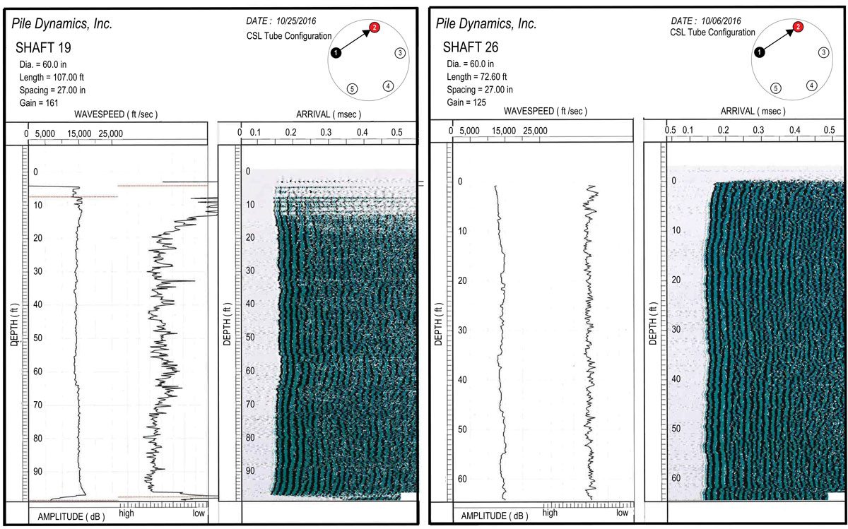
CSL Data: compromised drilled shaft on the left, sound drilled shaft on the right.
Each drilled shaft was evaluated using Crosshole Sonic Logging (CSL) in accordance with ASTM D 6760. The tests are performed by a transmitter probe that converts electrical pulses into ultrasonic waves. A receiver probe measures the ultrasonic waves. The probes are sent down parallel steel pipes that are cast in the shafts. There are a total of five pipes for CSL per drilled shaft. The CSL data indicated possible flaws in the top 8 feet of one shaft and the top 3 feet in the other shaft.
Although core samples taken from the center of shafts did not reveal flaws, the concern was about the cover around the reinforcing cage. Thus, a request was made for the top four feet of the shafts to be exposed for visual observation, where moderate-sized chunks of concrete from the loose fill were found embedded in the sides of the shaft. The contractor was then required to probe the six inches of concrete cover using a rotor hammer drill with the longest available drill bits. On more than one occasion, while drilling vertically into the cover, the concrete offered little to no resistance. Also, the air from the drill would periodically force water out of holes on the opposite sides of the shaft. This process revealed weak, porous concrete cover of the shafts.
Drilled Shaft Repair
The design team had little confidence that these shafts had adequate corrosion protection for the reinforcing steel, and were thus considered unreliable for long-term performance. Consequently, the capacity of these drilled shafts had to be replaced. The solution preferred by the contractor was to drive H-piles locally around the compromised shafts to replace the missing capacity. However, even with as many H-piles as could physically fit within the mat foundation geometry, this solution was not practical because of the stiffness incompatibility between the new H-piles and the adjacent drilled shafts. Variations of the repair option to excavate, remove the concrete cover, and re-cast concrete were attempted, but ultimately were abandoned because of worker safety and constructability concerns. One option dismissed early on in the process was revisited – to core the center of each drilled shaft and insert a concrete-filled steel pipe through the region of the compromised shaft. This was made possible only by an ability to core a large diameter hole in the center of the existing shaft using a rock auger without interfering with the existing reinforcing cage.
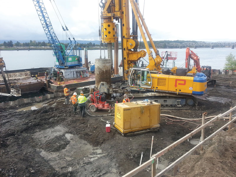
Installation of drilled shaft.
Ultimately, a 36-inch diameter auger was used to core the center of each shaft a minimum of 12 feet below the location where it was believed, based on drilling and CSL data, each existing shaft was compromised. This allowed a 33-inch diameter x 1.25-inch thick steel pipe to be placed inside the core and extend 42 inches into the mat slab. Overall, a 28-foot length of pipe was needed for each shaft. This allowed the concrete-filled pipe to act over the compromised portion of the drilled shaft and ultimately transfer loads back to the existing shaft below.
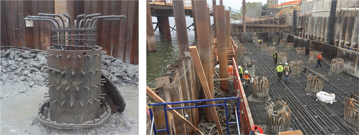
Foundation under construction: a repaired shaft (left) and bottom layer of reinforcement in mat slab (right).
The analytical model used in the original evaluation was revised using the structural properties of the repaired shaft, with particular attention given to the boundary conditions at the top of the pipe. Although there was an approximate 7% shift of axial demand to the adjacent uncompromised shafts, the concrete-filled pipe recovered most of the stiffness of the original shaft to make the compromised shafts effective. The analysis also showed that it was essential to develop as much bending capacity at the top of the pipe as possible to minimize the redistribution effect. Consequently, this bending resistance was achieved considering three components – the addition of a spirally tied reinforcing cage to help engage the concrete core of the pipe, the embedded portion of the pipe extension above the bottom layer of slab reinforcement, and headed studs added around the pipe perimeter to directly engage the pipe wall in bending. Additional detailing was needed in the mat slab to support the high local demands from the pipe flexure at the top. This bending moment at the bottom of the pipe was redistributed to the shaft by the socketed 12-foot embed length, where the shear demand to engage bending was limited to the shear capacity of the shaft reinforcement. This determined the effective embedment of the pipe in the competent portion of the original drilled shaft below.
Lessons Learned
During shaft excavation and repair, the engineers and the contractor suspected that the excavations for the drilled shafts encountered a local subsurface area fill that contained sizeable concrete rubble and large void areas. When these voids were exposed by the removal of the temporary casing, the concrete flowed into the voids.
The contractor’s sequence called for the drilled shafts to be constructed before excavation for the cofferdam tremie seal or mat slab. When the tremie seal and mat slab excavation occurred, the contractor pulled out broken concrete slabs in the vicinity of the problem shafts, validating the suspicions.
Drilled shaft repairs are expensive and time-consuming. The repair for the drilled shafts cost approximately 120% of the original drilled shaft installation. When projects are constrained by short in-water work periods, schedule delays can be particularly troublesome. For waterfront structures with deep foundations in areas of historic waterfront development, the risk associated with unknown and variable subsurface conditions is high. This risk can be partially mitigated by performing more exploratory geotechnical borings, or limited-depth potholing, than would be typical for an upland or undeveloped site.
The pre-design geotechnical borings performed at the site indicated fill and woody debris but did not indicate concrete. It is possible that a more comprehensive geotechnical exploration program would have alerted the designers to the concrete debris field, and provisions could have been established within the design documents (such as requiring permanent casing within the fill zone at the concrete debris field) to lessen the risk. However, designing to account for all unknowns can be expensive as well. The balance of risk associated with deep foundations is often the trickiest part of waterfront project development, and owners may not be fully aware of the risks. The construction of the Grant Street Pier foundation provides a case study in the potential risk associated with drilled-shaft deep foundations.▪
Dominic A. Webber, P.E., S.E,. is a Structural Engineer with BergerABAM, Inc. He is involved with building and marine structure design as well as design/build projects with geotechnical construction firms. Dominic can be reached at dominic.webber@abam.com.
Howard A. “Hod” Wells, P.E., LEED AP, ENV SP, is a Senior Project Manager with BergerABAM, Inc. He is involved with transportation and marine structure design in the Pacific Northwest. Howard can be reached at howard.wells@abam.com.