
Updated for 2018 IBC
From 2001 to 2012, the AISI Committee on Framing Standards developed nine different framing standards to cover specific aspects of cold-formed steel framing. Six of these standards addressed the design of structural elements, such as general provisions, wall studs, floor joists, trusses, headers, and shear walls. The other standards addressed such topics as a code of standard practice, the definition of standard product, and prescriptive design for residential applications. But, why would AISI develop six discrete framing standards as opposed to one design manual? This has been an often asked question by framing design engineers. The simple reason is, it was easier to develop small single-topic documents versus a more comprehensive multi-topic document.
But, in 2015, these six AISI cold-formed steel framing standards, AISI S200, S210, S211, S212, S213, and S214 (references 1 to 6), were consolidated into a comprehensive multi-topic standard, North American Standard for Cold-Formed Steel Structural Framing, AISI S240. This new standard includes design provisions for wall systems, floor and roof systems, lateral force-resisting systems, as well as truss and header assemblies.
It should be noted that the newly developed and updated AISI framing standards refer to AISI S100-12 (10), not AISI S100-16, due to the sequencing of the documents in the standard development schedule.
This article focuses on AISI S240 which applies to cold-formed steel structural members subject to gravity loading, wind loading, and seismic loading, except when specific seismic detailing is required. For nonstructural member design, AISI S220 governs the design (see STRUCTURE, February 2013) and when specific seismic detailing is required, AISI S400, North American Standard for Seismic Design of Cold-Formed Steel Structural Systems, is the applicable framing design standard. Additionally, the North American Standard for Cold-Formed Steel Framing – Product Data, AISI S201, provides criteria for standardized products, AISI S202 serves as the industry code of standard practice, and AISI S230 provides a prescriptive method for one- and two-family dwellings. These cold-formed steel framing standards are available as free downloads at www.aisistandards.org.
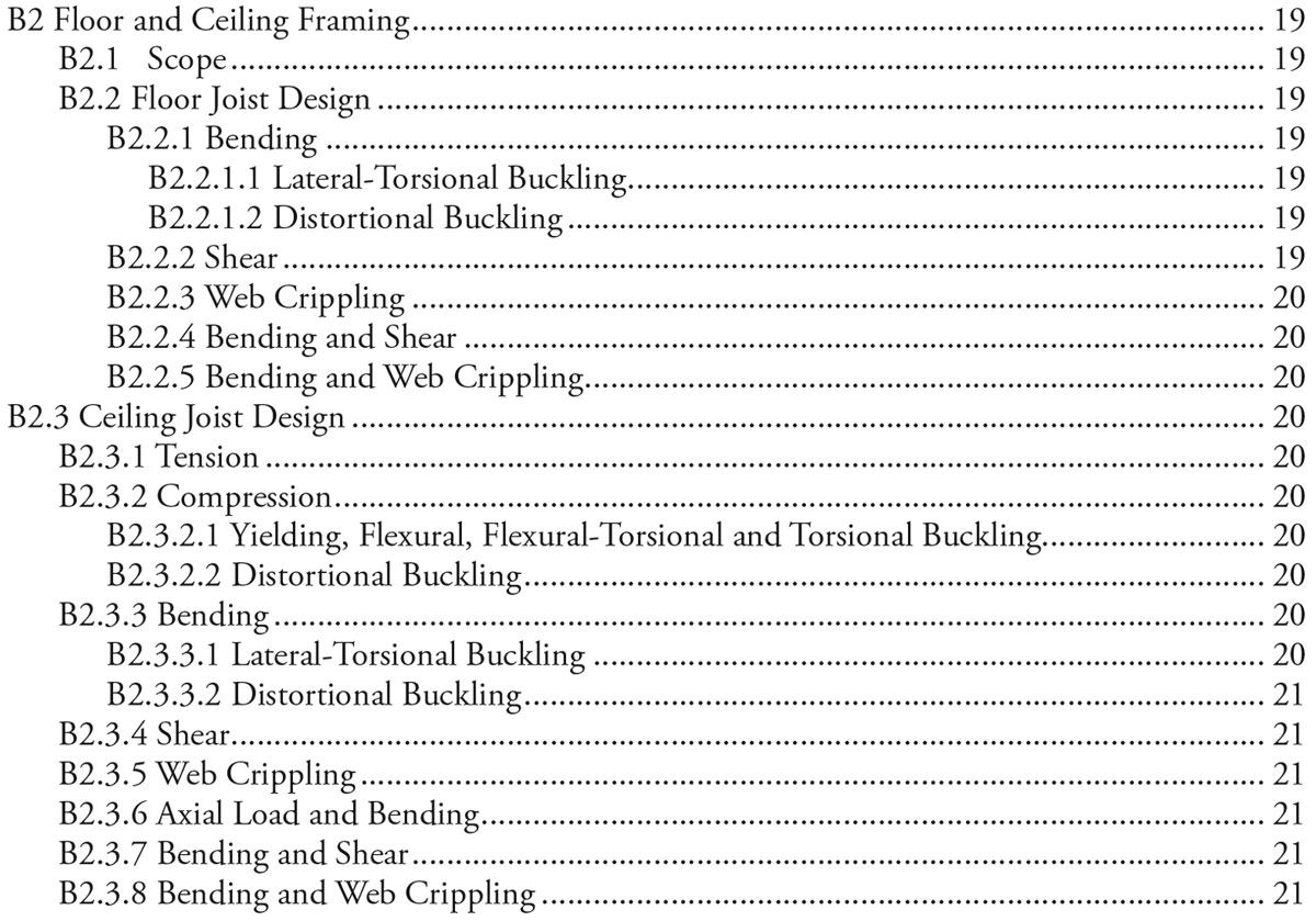
Table 1. Format defines design considerations.
The new AISI S240 standard has six topical chapters and two appendices. Within each topical area, the design considerations are sequentially ordered such that the document’s format serves as a pseudo flow chart that defines required design considerations (Table 1) as an aid for the design engineer.
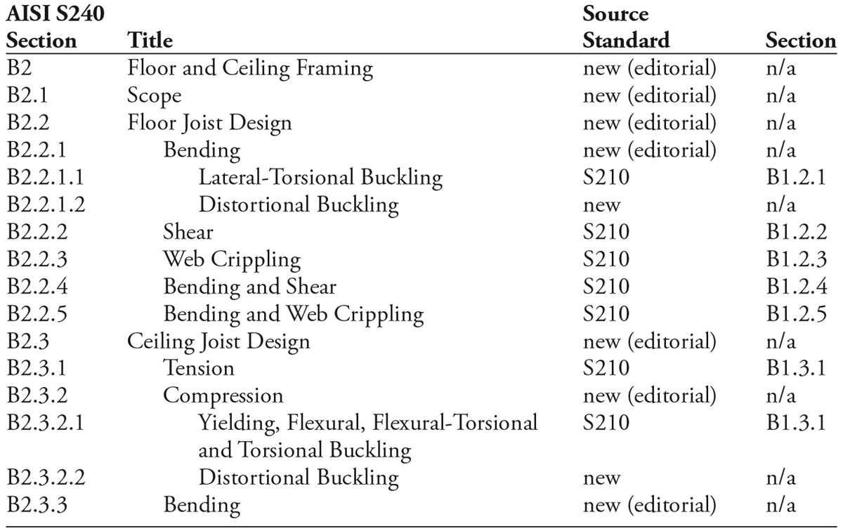
Table 2. Section reference table S240 and previous standard.
Also, for ease of use, S240 contains a section reference table between the S240 provisions and the previous provisions (Table 2).
Chapter A, General
This chapter contains general requirements as previously included in AISI S200. It outlines the scope, which is for design and installation of cold-formed steel framing of a) floor and roof systems, b) structural walls, c) shear walls, strap braced walls, and diaphragms to resist in-plane lateral loads, and d) trusses for load-carrying purposes in buildings. The chapter also includes:
- Definitions for terms used in the standard
- List of materials applicable to the framing members
- Corrosion protection requirements
- Framing products
- Reference documents
The previous design standards limited their application to framing members having a maximum base steel thickness to 118 mils (0.1180 inches or 2.997 mm). This limitation has been eliminated from AISI S240; however, it should be remembered that 118 mils is still the maximum thickness of standard products in the United States and 97 mils (0.0966 inches or 2.454 mm) is still the maximum thickness of standard products in Canada.
ASTM C955 has historically stipulated manufacturing tolerances for cold-formed steel structural framing members. These tolerances were replicated in AISI S200 in 2012 and are now included in AISI S240. In 2012, the manufacturing tolerance values were extended to the flange width and stiffening lip length.
Chapter B, Design
This chapter contains design provisions for cold-formed steel framing members and assemblies, as previously included in AISI S210, S211, S212, and S213.
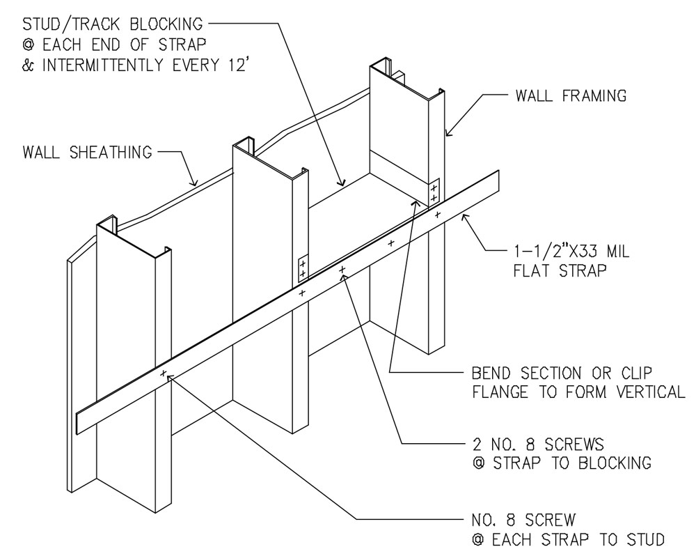
Figure 1. Sheathing and discrete bracing.
For curtain wall systems, the standard now permits the use of the bracing combination of sheathing attached to one side of the wall stud and discrete bracing for the other flange (Figure 1). The discrete braces are limited to not greater than 8 feet (2.44 meters) on center.
Built-up sections continue to be evaluated in accordance with Section D1 of AISI S100 [CSA S136]. However, AISI S240 now incorporates an exception for a built-up axial load bearing section comprised of two studs oriented back-to-back forming an I-shaped cross-section. The exception applies where the built-up section is seated properly in a track, and the top and bottom end bearing detail of the studs consists of a steel or concrete support with adequate strength and stiffness to preclude relative end slip of the two built-up stud sections. For such applications, the compliance with the following onerous fastener end connection provision of AISI S100 Section D1.2(b) is not required:
The ends of a built-up compression member are connected by a weld having a length not less than the maximum width of the member or by connectors spaced longitudinally not more than 4 diameters apart for a distance equal to 1.5 times the maximum width of the member.
This new exception provides for a more economical built-up member, as is often used as a jamb stud or shear wall boundary member.
For roof or floor diaphragms with a maximum aspect ratio of 4:1, framed with cold-formed steel and covered with non-steel sheathings, the in-plane nominal shear strength can be determined by tests in accordance with ASTM E455. The use of ASTM E455 results in higher nominal shear strength values as compared with the cantilever test method historically used for steel deck diaphragms. The test results are to be calibrated in accordance with AISI S100 using the statistical values given in AISI S240 Section B5.4.5.
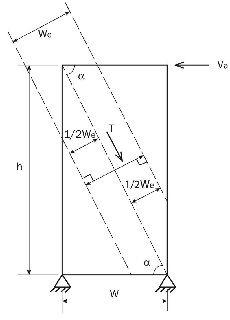
Figure 2. Effective strip method model for steel-sheet sheathing.
Beneficial for the design engineer is a new Effective Strip Method that enables the calculation of the nominal in-plane shear wall strength for Type I shear walls (Figure 2). The method assumes a sheathing strip carries the lateral load via tension field action. This computational method is applicable for walls sheathed with steel sheet. This method provides an alternative approach to determine the shear wall strength, especially for those that are outside the limitations of the tested systems. The effective strip method is permitted to be used within the following range of parameters:
a) Designation thickness of stud, track, and stud blocking: 33 mils (0.838 mm) to 54 mils (1.37 mm).
b) Designation thickness of steel sheet sheathing: 18 mils (0.457 mm) to 33 mils (0.838 mm).
c) Screw spacing at panel edges: 2 inches (50.8 mm) to 6 inches (152 mm).
d) Height-to-width aspect ratio (h:w): 1:1 to 4:1.
e) Sheathing screw shall be minimum No. 8.
f) Yield stress of steel sheet sheathing shall not be greater than 50 ksi (345 MPa).
Chapter C, Installation
This chapter provides installation requirements previously contained in the various framing standards.
Chapter D, Quality Control, and Quality Assurance
This newly developed chapter provides minimum requirements for quality control and quality assurance for material control and installation for cold-formed steel light-frame construction. Minimum observation and inspection tasks deemed necessary to ensure quality cold-formed steel light-frame construction are specified. The February 2016 issue of STRUCTURE contains a comprehensive discussion of Chapter D.
Chapter E, Trusses
This chapter contains design, manufacturing quality criteria, and installation requirements for cold-formed steel trusses as previously included in AISI S214.
Chapter F, Testing
This new chapter lists applicable AISI test standards for cold-formed steel framing members, connections, and systems.
Appendix 1, Continuously Braced Design for Distortional Buckling Resistance
This appendix contains requirements for the determination of the rotational stiffness that structural sheathing provides to framing members to facilitate the design for distortional buckling.
Appendix 2, Test Methods for Truss Components and Assemblies
The truss component structural performance load test and full-scale truss confirmatory test methods, previously included in AISI S214, are provided in this appendix.▪
References
AISI S200-12, North American Standard for Cold-Formed Steel Framing-General Provisions, 2012 Edition.
AISI S210-07 (2012), North American Standard for Cold-Formed Steel Framing–Floor and Roof System Design, 2007 Edition (Reaffirmed 2012).
AISI S211-07(2012), North American Standard for Cold-Formed Steel Framing–Wall Stud De-sign, 2007 Edition (Reaffirmed 2012).
AISI S212-07(2012), North American Standard for Cold-Formed Steel Framing–Header Design, 2007 Edition (Reaffirmed 2012).
AISI S213-07w/S1-09(2012), North American Standard for Cold-Formed Steel Framing–Lateral Design, 2007 Edition with 2009 Supplement (Reaffirmed 2012).
AISI S214-12, North American Standard for Cold-Formed Steel Framing–Truss Design, 2012 Edition.