
Next Step in Incorporating Masonry in Your FEM
Demonstrating the need for utilizing finite element modeling (FEM) and analysis (FEA) to accurately model, analyze, and efficiently design masonry wall systems was the subject of a STRUCTURE article in May of 2016. Hopefully, the reader used the information in the article and is well on their way to building FEM that include structural masonry elements. With that background, they should be ready to advance their design of masonry with the aid of FEM.
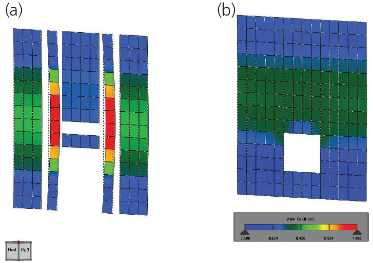
Figure 1. a) Traditional approach; b) New approach with FEM.
With FEM, even the simplest designs are better understood. What is the actual lintel force? What forces should be used to design the masonry jamb? How does the masonry system deflect under load? Traditional methods (Figure 1) have led to a conservative design that is effective but, with better tools (Figure 2), more efficient and accurate designs are possible.
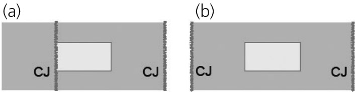
Figure 2. a) CJ next to opening; b) CJ away from opening edge.
Masonry Compressive Strength
The first place to start in developing a sophisticated FEM is to make every effort to define the material strength of all structural items correctly.
When using FEM, what design strength should be utilized? Since FEM associates load to elements based on their strength/stiffness, accuracy is crucial. Make every effort to model the actual masonry element strength. When designing structural elements with concrete masonry units (CMU), the compressive strength (f’m) of the assemblage of the block, grout, and mortar is crucial to the strength of the element. Sometimes, engineers will mistakenly specify a minimum f’m because the design will work at that value and they are not aware that higher design strengths are available; or, because they believe that masonry of lower strength will be easier to obtain.
Many manufacturers, however, regularly produce stronger blocks resulting in stronger structural members. Block manufacturers have increased the strength of CMU to reduce potential damage to units in production, storage, and site transportation. Knowing the actual strength of the material, and designing with it in mind, can lead to cost savings in both labor and materials. Visit www.forsei.com/cmudata for information on block strengths in several states.
The value of f’m affects numerous parts of masonry design. The modulus of elasticity of masonry is directly dependent on f’m, and for design, flexure, and shear checks that are performed against some percentage of f’m – a higher f’m means a higher allowable strength. This can mean less reinforcing steel and smaller members for lintel and jamb designs, wall design for axial loads and out-of-plane lateral loads, and in-plane loads on shear walls. A higher f’m will also reduce reinforcing lap lengths and, depending on the fastener, increase fastener capacity when connecting to the masonry, again reducing material costs.
Designing with the actual strength of the block that will be used on a project can be very beneficial and cost effective, especially for projects with a lot of openings or other details that create a complex masonry system.
Control Joints
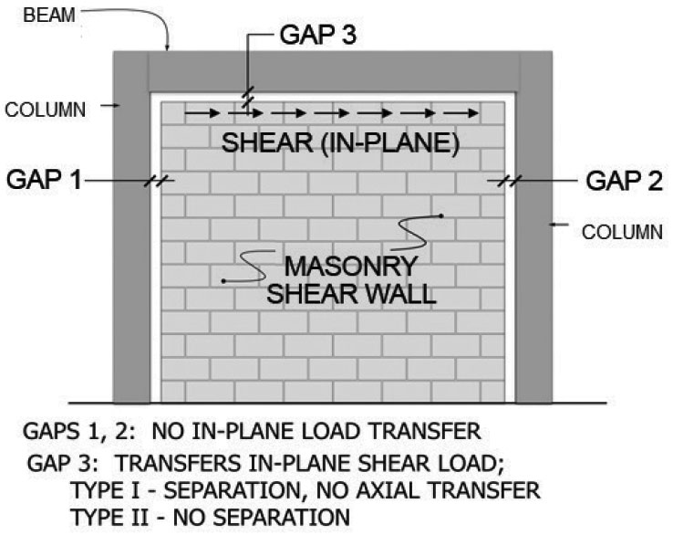
Figure 3. Hybrid design of masonry wall and surrounding frame.
Since the purpose of a control joint (CJ) is to provide a bond break that will permit longitudinal movement and relieve horizontal tensile stresses, horizontal reinforcing is generally not continuous through a control joint. Therefore, it makes sense for the structural engineer to locate the joints so that they will have as little impact as possible on wall capacity, within prescribed spacing recommendations. Many times, with limited methods for analyzing elements, structural engineers have used CJ in structural masonry walls to simplify the wall design. Designing simple walls (Figure 3) would be much easier to do with more primitive methods. A wall with a simple opening in the center (Figure 4b) would require a more advanced tool, such as an FEM.
If the wall in Figure 2 is 24 feet long and has an 8-foot wide opening centered within it, reinforcing around the opening will allow the wall to be designed as a 24-foot long perforated shear wall (Figure 2b) as opposed to two separate eight-foot long walls (Figure 2a). This design can be performed in software packages like ETABS 2016, RISA 3D, and RAM Elements.
The National Concrete Masonry Association (NCMA) has prescriptive requirements that recommend that control joints be spaced at 25 feet or 1.5 times the height of the wall, whichever is less. Joints located at areas of stress concentrations such as changes in wall height or thickness, or near wall openings or corners, are also recommended. Many of these requirements were based on past performance and unreinforced walls, and may or may not apply as well to today’s reinforced walls. Paying attention to these requirements and adding some reinforcing can result in the need for fewer construction joints. An alternative to the prescriptive requirements is to use an engineered method, again as outlined by NCMA TEK 10-3. This method accounts for the effect of reinforcing in the wall and may result in options with no control joints in the wall.
One of the likely spots for stress concentrations, and therefore a good candidate for control joints in unreinforced walls, is at wall openings. However, if the opening is essentially surrounded by reinforcing – that is, jamb reinforcing on each side, lintel reinforcing, and sill reinforcing (if applicable) – the wall around the opening can be considered sufficiently strengthened to avoid stress concentrations and control joints can be placed away from the opening to meet the minimum spacing listed above. Control joints should be spaced at least two feet from openings if possible (not required, but recommended) to allow for this reinforcing. This procedure will also enable the designer to take into account the full length of the wall when checking capacity.
Shear Wall Performance
It is important to consider control joints during the design of the lateral force resisting system. In Figures 1a and 1b, it is easy to see where to locate CJs to gain capacity in the design. Other locations to gain capacity are in stair and elevator core walls. When eliminating control joints in wall groups, the designer benefits from the stiffness of a box shape rather than just a few individual short walls. For example, a masonry core when analyzed as a box can have a moment of inertia nearly three times greater than if it were analyzed as just the individual walls. Even in a typical wall, it is advantageous to space control joints as far as possible in order to have longer wall panels. A 48-foot long wall, for example, could have four CJs spaced at 12 feet or three joints spaced at 16 feet. If the wall is eight-inch CMU and 20 feet tall with an f’m of 2000 psi, the option with four 12-foot walls has an in-plane design capacity of 4*50 = 200 kips total, while the option with the three 16-foot walls has a capacity of 3*93 = 279 kips. This represents a 39% increase in strength just from spacing the control joints farther apart.
As previously stated, NCMA also has recommendations on eliminating control joints altogether by providing sufficient horizontal reinforcing in the wall. These recommendations are usually met when horizontal reinforcement (joint reinforcement or bar reinforcement) is added, such as when designing walls for seismic or high wind requirements, or walls with many openings where continuous lintel reinforcement can be provided. When designing in areas with low seismic forces and few windows, it is usually not cost-effective to provide enough horizontal reinforcing to eliminate joints.
The in-plane shear (shear wall) capacity of a masonry wall is typically sufficient because of the reinforcing already required from other loading scenarios like out-of-plane bending or axial loading. This is certainly true when you have perimeter walls on all sides of a single-story building. Shear wall designs for masonry only start to require additional reinforcement for relatively tall buildings or certain other situations with low axial loads and low out-of-plane bending.
In every situation, it is important for control joints to be shown on the structural drawings rather than allowing the contractor to locate them in the field during construction. This way, the designer can locate them to provide greater structural stiffness, which can ultimately save money on the project.
Hybrid Design
FEM is an excellent way to model masonry infills that are designed to take the shear load, commonly referred to as a hybrid design. With frame members on each side, the masonry in the system can contribute significantly to the overall load resistance of the structure.
In fact, with Type II hybrid design where the masonry is built tight to the beam above (no gap), the masonry shares in the axial load support with the frame surrounding the wall. With multiple materials involved, the best tool to account for the load distribution in a thorough structural analysis is an FEM.
With box-shaped wall groups, hybrid masonry frames, or other shear wall considerations, having finite element software such as RAM Elements V8i and RISA 3D is essential to appropriately account for masonry’s actual stiffness and design strength. With finite element software, walls with openings can easily be considered as shear walls when they might have been previously ignored because of the complex analysis required. With these programs, engineers can recognize the strength of perforated masonry shear walls, hybrid masonry design, and stair and elevator shafts. As a result, masonry is more effective for masonry shear walls, and more accurate analysis leads to more precise and efficient design.
In seismic design situations, masonry walls do require particular attention to detailing similar to other concrete products, especially as you move from an ordinary reinforced masonry wall to a special reinforced masonry wall. Again, even with seismic loading, there are no provisions in the code to make the wall thicker simply because of seismic design. In fact, a lighter, thinner reinforced wall performs better in seismic regions, so reinforced 8-inch masonry can be a better choice than thicker walls.
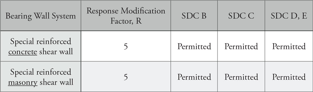
Excerpt from ASCE 7-10 Table 12.14-1.
Masonry is exceptional at resisting lateral load, as defined by the structural engineers standard for determining loads, ASCE 7. In this document, masonry is not only allowed to be used in seismic loading situations, but it also gives special reinforced masonry walls the same Response Modification Factor value as a special reinforced concrete shear wall in bearing wall situations. When reinforced and detailed properly, masonry walls are equivalent to concrete walls of equal strength, even in the most extreme in-plane shear loading situations that result from seismic events.
Lintels
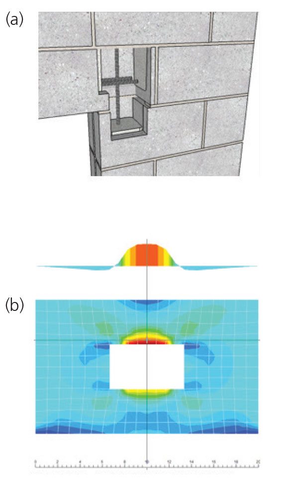
Figure 4. a) 3D image of masonry lintel/jamb reinforcement; b) Plate stresses used to determine lintel moment.
Masonry lintel analysis and design in an FEM are evaluating an area of the plate/wall mesh used for analyzing a masonry wall. With FEM, you do not create a separate entity for a masonry lintel. Rather, the lintel is part of the wall which most accurately represents the real wall structure. The masonry lintel creates an integral joint with vertical jamb reinforcement. This leads to a more robust design over other lintel solutions that consider the lintel separate from the wall (Figure 4a). The loads used in the design of lintels are actual wall forces generated by the finite element analysis of the wall (Figure 4b).
In the FEM, because of the integral nature of the lintel with the plate elements that represent the wall around the lintel and opening, the forces generated will be similar to a fixed end beam. This will create the need in masonry lintels for top and bottom reinforcement due to the positive and negative moment determined from the analysis.
Similar to the discussion above regarding perforated shear walls, the lintel areas of the wall are also participating elements in lateral resistance. This allows for the creation of the perforated shear wall which has more overall capacity than separate shear walls on each side of the openings. This requires the lintels to be designed for lateral loads as part of the overall integral masonry system.
Conclusion
From integrated lintels and hybrid masonry frames to perforated shear walls and boxed wall group shear walls, FEM is the tool necessary to advance the analysis and design of masonry. This is creating new trends in the use of masonry in building design.
Masonry is once again becoming a structural system that engineers across the country can more fully understand and utilize to provide efficient designs for many building types, thanks to new tools from FEM.
In the words of G.K. Chesterton: “I am the man who with the utmost daring discovered what had been discovered before.” Perhaps with the capabilities of FEM, we have rediscovered what has always been obvious – masonry is an excellent structural system.▪
Resources
The number one request from the May 2016 article has been actual examples of utilizing masonry in finite element programs. The space to include those examples is not available here, but manuals for specific software programs with these examples in mind can be downloaded. Along with examples of how to incorporate masonry into specific FEA programs, examples for the general topics presented in this article are also provided:
Pre-processing and modeling examples
1) How to account for cracking
2) How to account for partial grouting
3) The best way to incorporate CJ locations
Post-processing
1) How to extract results
2) How is an FEA reporting lintel forces, and are they right?
3) What is a masonry jamb, and what needs to be considered for design?
You can download these manuals at www.forsei.com/masonry.