
Part 2: Wood Diaphragm and Shear Wall Flexibility
Important design considerations and traditional approaches related to the design of a five-story wood-framed structure over a two-story concrete or masonry podium were addressed in Part 1 of this series (January 2017, STRUCTURE). The goal of this article is to help engineers better understand flexibility issues associated with these types of structures and how they can affect the design process.
Complex building shapes and footprints are driving design procedures and code requirements to evolve for all lateral resisting systems and materials. Associated research and full-scale testing are in turn causing some engineers to consider refining their techniques beyond traditional methods of design. Until fairly recently, wood structures tended to be straight forward in shape and size, with ample opportunity for shear walls and structural redundancy.

Figure 1. Typical mid-rise multi-story floor plans.
As increasingly complex building geometries and floor plans similar to those shown in Figure 1 are becoming more prevalent, there becomes a greater need to consider relative stiffness of the lateral-resisting elements and their impact on force distribution through the structure. A variety of challenges often occur on projects due to fewer opportunities for shear walls (e.g., more glass and larger openings at exterior wall lines), increased building heights, and multi-story shear wall effects. Although challenging, efforts are being made to bring greater awareness to these issues and to create guidance for more rational designs.
Diaphragm Flexibility – Seismic
Requirements for considering relative stiffness of diaphragms and shear walls have been in building codes for decades. Section 1604.4 of the 2015 International Building Code (IBC) requires, in part, that the total lateral force shall be distributed to the various vertical elements of the lateral force-resisting system in proportion to their rigidities, considering the rigidity of the horizontal bracing system or diaphragm. In the American Wood Council’s (AWC’s) 2015 Special Design Provisions for Wind and Seismic (SDPWS), Section 4.2.5 gives additional requirements for Wood Structural Panel (WSP) sheathed diaphragms. Seismic-specific requirements are found in ASCE 7-10, Section 12.3.1, which requires structural analysis to consider the relative stiffness of the diaphragms and the vertical elements of the seismic force-resisting system. Provisions for determining diaphragm flexibility under seismic forces are addressed in IBC Section 1604.4, ASCE 7-10 Section 12.3, and SDPWS Section 4.2.5.
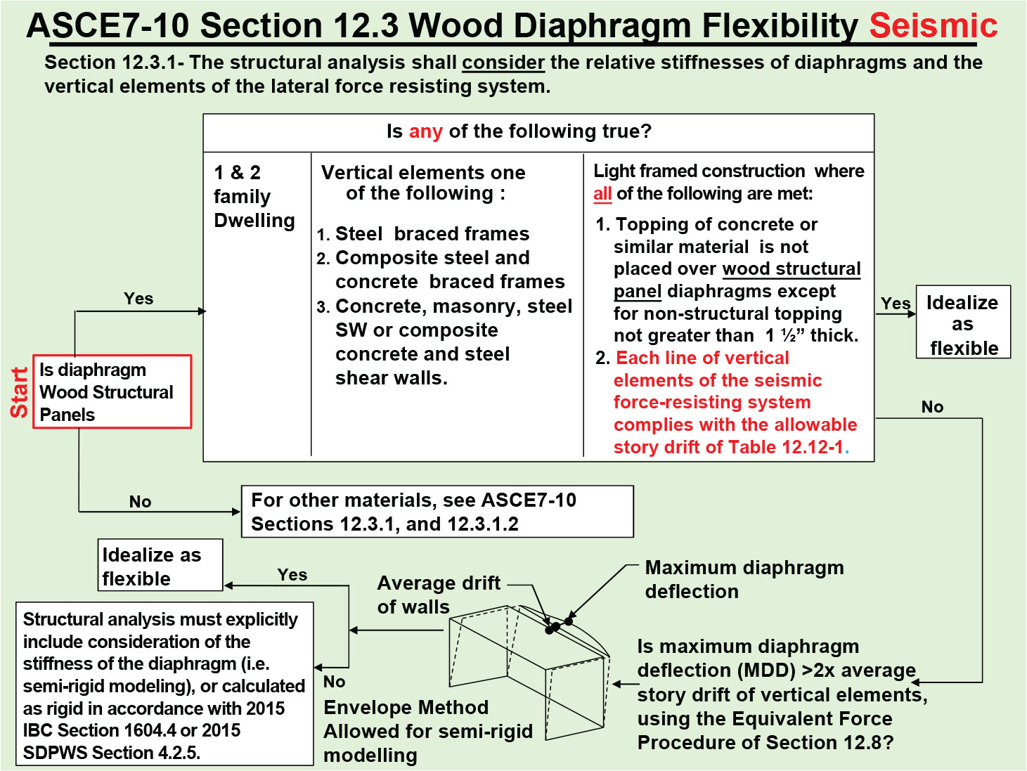
Figure 2. Wood diaphragm flexibility – seismic.
Flexible diaphragms are dealt with in ASCE 7-10, Section 12.3.1.1. Diaphragms constructed of WSP are permitted to be:
- Idealized as flexible provided they meet ASCE 7-10 Section 12.3.1.1 (c), which includes meeting allowable story drift limits at each line of lateral force-resistance as noted in the flow chart shown in Figure 2, or
- Idealized as flexible where the computed maximum in-plane deflection under lateral load is greater than two times the average story drift of adjoining vertical supporting elements of the lateral force-resisting system, in accordance with Section 12.3.1.3 and Figure 12.3-1.
Distribution to the vertical force-resisting elements for flexible diaphragms is based on tributary area.
Although WSP-sheathed diaphragms are commonly assumed to be idealized as flexible, there can be conditions where a diaphragm does not qualify for flexible diaphragm analysis via ASCE 7-10 Section 12.3.1 (c) – i.e., when shear walls with adequate seismic force capacity are provided, but there is not enough wall stiffness to meet the allowable story drift as a wall line. ASCE 7-10 Commentary, Section C12.3.1.1 – Flexible Diaphragm Condition, states that compliance with story drift limits along each line of shear walls is intended as an indicator that the shear walls are substantial enough to share the load on a tributary area basis and not require torsional force redistribution. With very flexible exterior walls, lateral loads will partially shift to the corridor walls, differing from the load distribution by a flexible diaphragm assumption.
Wood diaphragms are sometimes treated as open front or cantilever where a capable shear wall line is not provided on the exterior of the building. Open front structures are covered in SDPWS Section 4.2.5.2. This section requires that, for loading parallel to the open side, diaphragms shall be modeled as semi-rigid or idealized as rigid, and the story drift at each edge of the structure, not just the center of mass, shall not exceed ASCE 7-10 allowable story drift. The applied seismic forces for drift checks of open front diaphragms should include torsion and accidental torsion. The drift calculations shall include shear and bending deformations of the diaphragm and be computed on a strength level basis amplified by Cd. Flexible diaphragms cannot be used for open front structures because they cannot transfer torsional forces.
Rigid diaphragms are addressed in IBC Section 1604.4, ASCE 7-10 Section 12.3.1.2, and SDPWS Section 4.2.5. In accordance with IBC Section 1604.4, a diaphragm is rigid for the purpose of distribution of story shear and torsional moment when the lateral deformation of the diaphragm is less than or equal to two times the average story drift. In a rigid diaphragm analysis, distribution is based on the relative stiffness of the vertical-resisting elements of the story below. Compared to a similar flexible diaphragm analysis of a typical multi-family central corridor layout, the rigid diaphragm analysis distributes more load to the corridor and transverse walls while reducing the load distribution to the more flexible exterior walls. The loads in the diaphragm see a similar shift between the two analysis methods.
For semi-rigid modeling, the distribution of forces to the vertical resisting elements is based on the relative stiffness of the diaphragm and the vertical resisting elements below, accounting for both shear and flexural deformations. In lieu of a semi-rigid diaphragm analysis, SDPWS 4.2.5 permits the use of an enveloped analysis, where the diaphragm force distribution to the vertical elements is the larger of the resulting shear forces analyzing the diaphragm as flexible and rigid. A semi-rigid analysis is always an acceptable method of analysis and is considered a valid path to code compliance.
Diaphragm Flexibility – Wind
Diaphragm flexibility requirements for wind conditions are embedded within the definitions of ASCE 7-10 Section 26.2 – Definitions, DIAPHRAGM, which states that diaphragms constructed of WSP are permitted to be idealized as flexible. It should be noted that, under wind loading, an open front diaphragm configuration is possible. Although not required for wind, following SDPWS 4.2.5.2 is considered good engineering practice, including constructing the diaphragm to meet semi-rigid or rigid stiffness requirements and showing that the resulting drift at the edges of the structure can be tolerated. It is also important to note that under the wind provisions of ASCE 7-10, Chapter 27, Section 27.5.4 – Diaphragm Flexibility, requires that the structural analysis shall consider the stiffness of diaphragms and vertical elements of the main wind force resisting system (MWFRS).
Shear Wall Stiffness
Shear wall stiffness can have a significant effect on the distribution of shear forces through the diaphragm. It has become increasingly difficult to find exterior walls that can be used as shear walls due to diminishing wall lengths, larger openings, and building offsets. Force distribution to individual shear wall segments in each line of lateral-force resistance shall provide the same calculated deflection per SDPWS Section 4.3.3.4.1 (i.e., distribution by stiffness), regardless of whether they are inline or offset. Optionally, where the nominal shear capacity of sections exceeding an aspect ratio greater than 2:1 are multiplied by 2bs/h, shear distribution shall be permitted to be taken as proportional to the shear capacities of individual full height wall segments. This method results in the long-used method of distributing load to walls based upon their length.
Shear wall deflections are permitted to be calculated using the familiar SDPWS three-part deflection equation 4.3-1 or four-part equation C4.3.2-1. These equations are based on an idealized single-story shear wall with a horizontal shear force applied at the top of the wall. For example, the first term, addressing bending, is the deflection resulting from a lateral shear force, but not a bending moment applied at the top of the wall. Extending the basic equations to designs with four, five, or even six stories of WSP-sheathed shear walls is a process of incorporating multi-story wall effects. Examples of the practical application of multi-story shear wall design can be found in the Structural Engineers Association of California (SEAOC) Structural/Seismic Design Manual – Volume 2 and Woodworks Five-story Wood-frame Structure over Podium Slab. These examples follow what is sometimes called the traditional multi-story shear wall method, as it is a straightforward extension of what has commonly been used for two- and three-story buildings for decades. Other multi-story deflection calculation methods have been discussed, such as by Hohbach and Shiotani and the more recent “mechanics-based” approaches suggested by FPInnovations in Canada. Both of these approaches use a behavioral model where the shear walls essentially cantilever off of their foundation with the floor levels contributing little rotational stiffness in the plane of the walls, predicting higher deflections and more flexible walls than traditional methods. These methods take rational engineering approaches to account for multi-story effects which are not explicitly delineated in codes and standards. The decision to use such methods is currently left up to engineering judgment, preference, or the desire to improve or refine current design practices.
Horizontal Distribution of Shear
The combined effects of diaphragm and shear wall flexibility, multi-story shear wall effects, offsets in the diaphragm, and presence of exterior shear walls all affect horizontal distribution of forces within the diaphragm and to the vertical force-resisting elements. Consideration of the relative stiffness of the lateral-resisting elements becomes very important under these conditions.
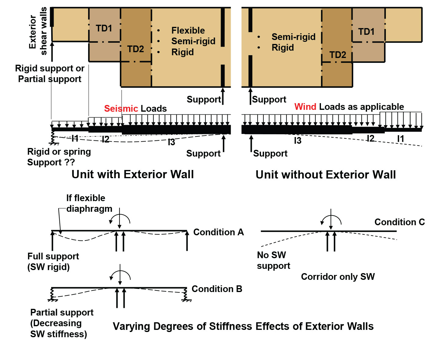
Figure 3. Horizontal distribution of shear.
The partial unit plans in Figure 3, representing highlighted units shown in Figure 1, demonstrate the types of units that might be found in a modern mid-rise, multi-residential structure. One is shown with exterior walls and the other as an open front with no exterior walls. Each unit is shown to have multiple horizontal offsets in the diaphragm.
If the exterior shear walls in the unit on the left can meet allowable story drift, they can be assumed to be stiff enough to allow a diaphragm to be idealized as flexible and the load distributed to these walls can be based on a tributary area basis, as shown in Condition A. Once exterior wall lengths are reduced, or large openings are placed in the walls, they start losing stiffness and transfer more forces to the corridor walls. When this occurs, they provide only partial support, as shown in Condition B. This process could continue to a point where story drift limits cannot be met, which would require a semi-rigid or rigid analysis to be performed. Using rigid analysis is only an option if justified by calculation. With very narrow, flexible exterior shear walls, under some conditions, distribution of forces can result in almost no load going to the exterior walls in the upper stories, in effect creating diaphragm behavior similar to that of a cantilever diaphragm as shown in Condition C.
Figure 3 schematically shows that horizontal offsets in the diaphragm could also affect shear force distribution due to changes in diaphragm stiffness brought about by differing depths at the offsets. As diaphragm stiffness decreases, more of the forces are transferred to corridor walls and less to exterior walls. Continuity must be maintained across the offsets to create complete lateral load paths and transfer diaphragm forces to supporting exterior walls.
Conclusion
All designs are required to be based on a rational analysis using accepted principals of engineering mechanics. It has become increasingly important to consider the relative stiffness of diaphragms and shear wall multi-story effects as buildings get taller and more complex in shape.▪