
Part 2: How to Select a Reinforced Concrete Floor System
Reinforced concrete floor systems provide adequate resistance to vibration caused by a variety of sources because of their inherent mass and stiffness. General information on sources of vibration and acceptance criteria for typical office and residential occupancies was covered in Part 1 (STRUCTURE, September 2017). Vibration characteristics of reinforced concrete flat plate and wide-module joist systems were also discussed in Part 1, with useful guidelines to quickly ascertain when these reinforced concrete systems are adequate for various types of vibration excitations.
Flat plate voided concrete systems and two-way joists (waffle slabs) are covered in this second article. Vibrational characteristics of these systems are provided, as are guidelines on how to select the appropriate system based on span, load, and source of vibration.
Vibration Characteristics
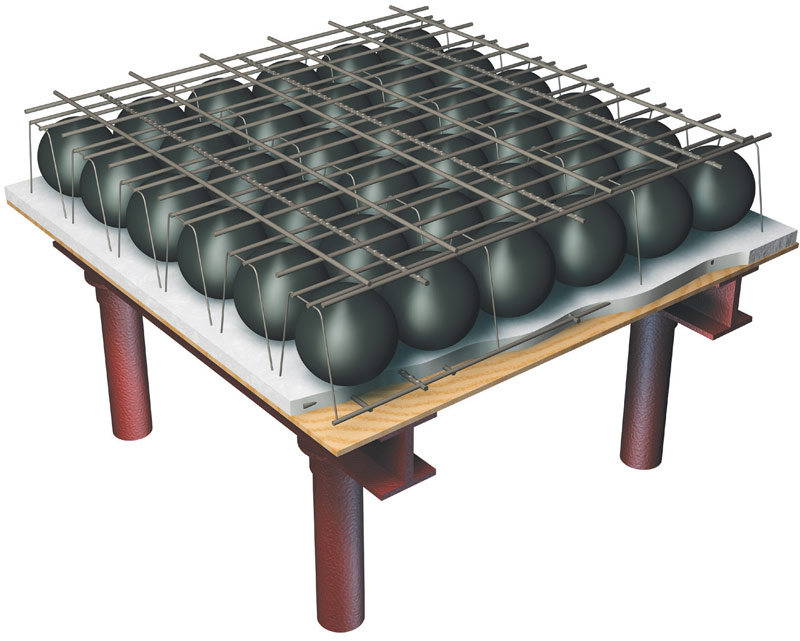
Figure 1. Flat plate voided concrete slab system.
As noted in Part 1, the stiffness of a floor system plays a key role in its ability to counteract the effects of vibrations. The main component of deflection in a reinforced concrete floor system is from flexure. Stiffness, which is proportional to the inverse of deflection, can be calculated using the modulus of elasticity of the concrete, Ec, and the effective moment of inertia, Ie. The dynamic modulus of elasticity can be used to calculate floor stiffness, which can conservatively be taken as 1.2 times the static modulus Ec, which is given by ACI 318-14 Equation (19.2.2.1.a).
A flat plate voided concrete slab system is a two-way reinforced concrete system of uniform thickness that contains regularly-spaced, hollow, plastic balls made of high-density, recycled polyethylene (HDPE) inside the concrete (Figure 1). The plastic balls are commonly referred to as void formers and are usually spherical or ellipsoidal in shape. Void formers are positioned within wire support cages to create modular grids (cage modules), which are locked between the upper and lower reinforcement layers in the concrete slab. These grids are judiciously located in zones where concrete is not needed and where flexural strength and load transfer to supports are not compromised. Depending on the size and distribution of the void formers, the weight of a flat plate voided concrete slab can be up to 35% lighter than a solid slab of the same thickness. Flat plate voided concrete slab systems are essentially flat plates with regularly-spaced voids and, thus, can be designed just like any two-way slab system. It was shown in Part 1 that, for flat plate systems, Ie of a panel section can be calculated based on the average effective moments of inertia of the column and middle strips that make up the panel.
ACI Equation (24.2.3.5a), which is a function of the cracking moment, Mcr, can be used to determine Ie for the design strips. It is recommended to use fr = 4.5λ√f’c instead of fr = 7.5λ√f’c when calculating Mcr because of the relatively low reinforcement ratios in flat plate voided concrete slab systems.
The effective moment of inertia, Ie, is also a function of the gross moment of inertia of the section, Ig. The gross moment of inertia of a flat plate voided concrete slab system is less than that of a solid slab because of the embedded void formers. In general, Ig depends on the shape, size, and spacing of the void formers. Manufacturers’ literature can be used to obtain gross moments of inertia for flat plate voided concrete slab systems.
In the case of two-way joists, the same equation for flat plates can be used to calculate Ie, with the exception that Mcr is determined using fr = 7.5λ√f’c. It is common to transform a two-way joist system into a two-way system of uniform equivalent thickness. The equivalent thickness is determined by setting the gross moment of inertia of the actual cross-section of the two-way joist system equal to that of an equivalent section that has a uniform thickness, he.
The effective mass (or weight) of a floor system is required when determining its natural frequency. Damping, which is a measure of how quickly vibration will subside and eventually stop, also plays a key role in vibration analysis. These quantities are covered in Part 1.
The natural frequency, fn, of a floor system is related to mass and stiffness and is utilized in all vibration analyses, including checking that applicable acceptance criteria are satisfied. Simplified techniques can be utilized to determine fn instead of performing a finite element analysis. In the case of flat plate voided concrete slab systems, the system can be modeled as a thin, isotropic plate, which is free to deflect at any point except the columns. The equation for fn can be found in the article titled Vibration of Reinforced Concrete Floor Systems (STRUCTURE, April 2015), by the authors. A simplified equation for two-way joists can be found in the same article. In both cases, the approximate fn are at most 10% less than those from a finite element analysis. These equations can be utilized in the preliminary design stage to quickly ascertain whether the floor system is best suited to satisfy the required vibration criteria.
When to Select These Systems
As discussed in Part 1, parametric studies were performed to determine the conditions under which vibration acceptance criteria were satisfied for flat plate voided concrete systems and two-way joist systems. The following assumptions were used in the analyses:
- Normal weight concrete with f’c = 4,000 psi
- Grade 60 reinforcing bars
- Superimposed dead load = 10 psf
- Live load varies from 40 to 100 psf
- Actual live load from 6 to 11 psf
- Damping ratio = 0.03
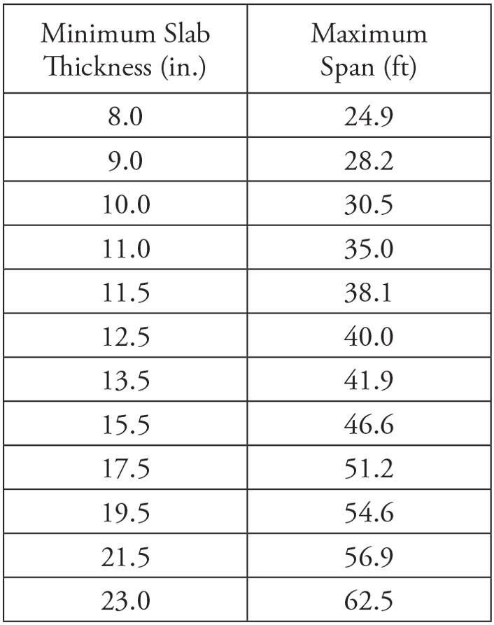
Table 1. Minimum slab thickness/maximum span lengths for flat plate voided concrete systems subjected to walking excitations.
For both floor systems, acceptance criteria for walking excitations are easily met. Maximum span lengths that satisfy the acceptance criteria for walking excitations for flat plate voided concrete systems as a function of slab thickness are given in Table 1. Maximum span lengths for two-way joist systems based on total thickness (4.5-inch slab thickness plus the thickness of the rib) are shown in Table 2. In short, acceptance criteria for walking excitations are satisfied for typical flat plate voided concrete systems and two-way joist systems that satisfy minimum requirements for deflection.

Table 2. Minimum total thickness/maximum span lengths for two-way joist systems subjected to walking excitations.
Maximum span lengths for flat plate voided concrete systems based on three types of rhythmic excitations are given in Table 3. Table 4 contains maximum span lengths for two-way joist systems.
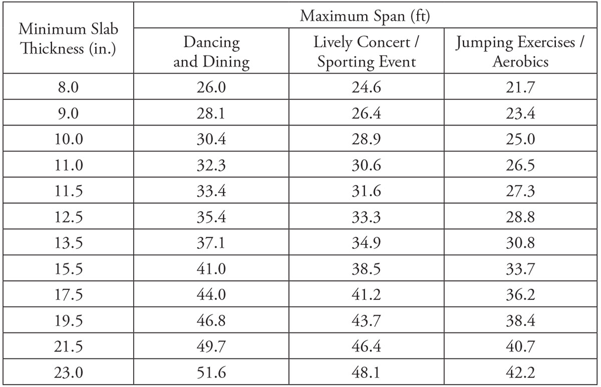
Table 3. Minimum slab thickness/maximum span lengths for flat plate voided concrete systems subjected to rhythmic excitations.
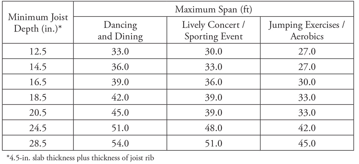
Table 4. Minimum total thickness/maximum span lengths for two-way joist systems subjected to rhythmic excitations.
Flat plate voided concrete systems and two-way joist systems can satisfy the acceptance criteria for sensitive equipment that have limiting vibrational velocities over an extensive range. Table 5 contains a summary of the maximum span lengths and required slab thicknesses for flat plate voided concrete systems assuming a fast walking pace. Given in Table 6 are the maximum span lengths of two-way joist systems as a function of minimum total thickness and a fast walking pace.
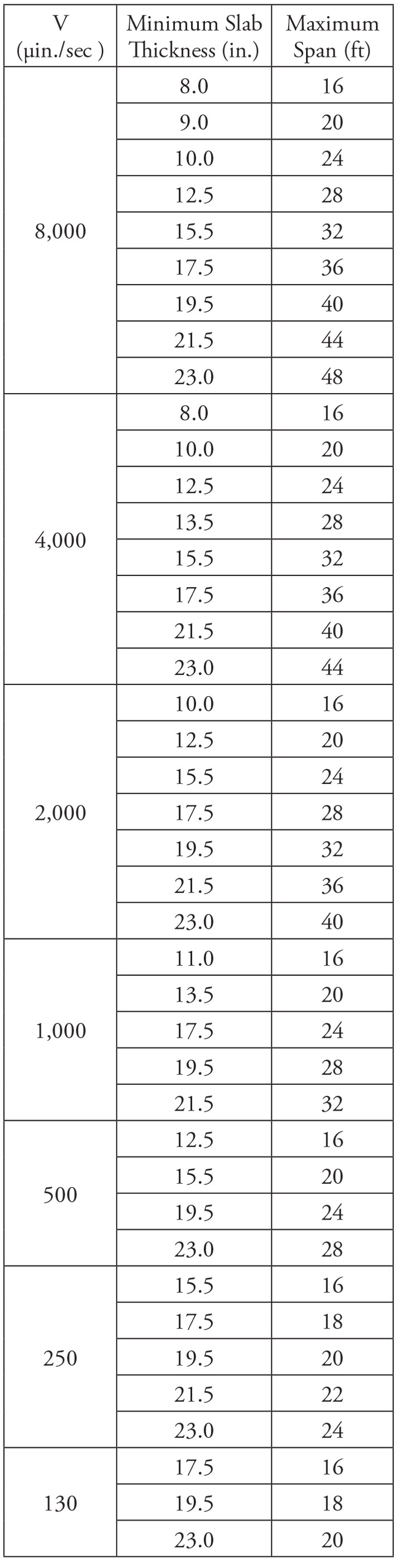
Table 5. Minimum slab thickness/maximum span lengths for flat plate voided concrete systems as a function of limiting vibrational velocities V.
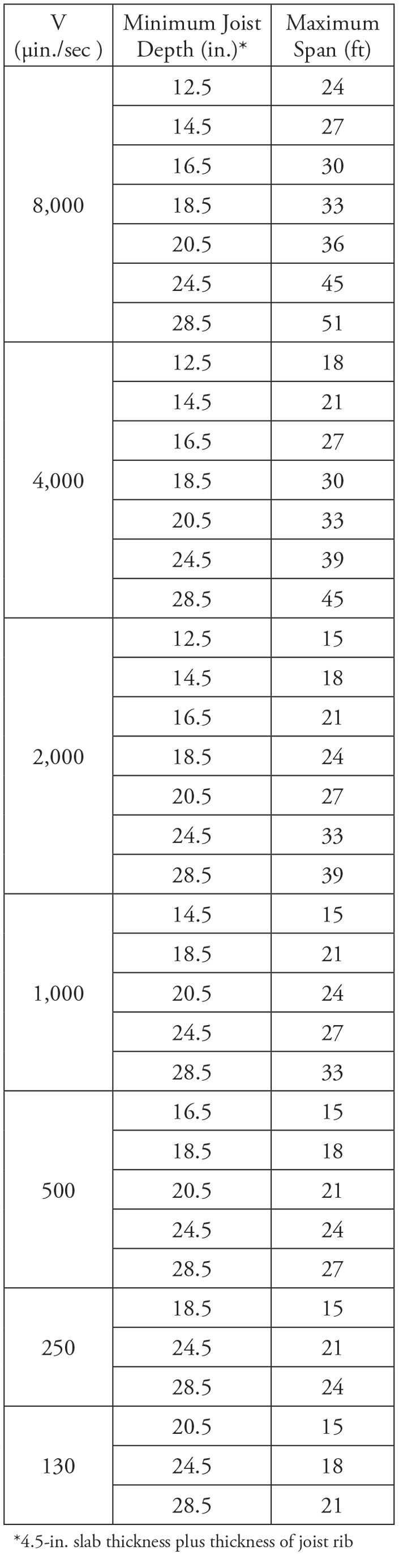
Table 6. Minimum total thickness/maximum span lengths for two-way joist systems as a function of limiting vibrational velocities V.
The information presented in these tables can be used to quickly ascertain whether a flat plate voided concrete system or a two-way joist system is suitable for a given set of constraints. The results from the parametric study are not meant to take the place of a more refined analysis; the main purpose of the study is to provide information that will assist the design professional in making a rational decision on a suitable reinforced concrete floor system for vibrations.▪
References
ACI (American Concrete Institute). 2014. Building Code Requirements for Structural Concrete and Commentary. ACI 318-14, Farmington Hills, Michigan.
CRSI (Concrete Reinforcing Steel Institute). 2014. Design Guide for Vibrations of Reinforced Concrete Floor Systems. Schaumburg, IL.
Scanlon, A. and Bischoff, P.H. 2008. “Shrinkage Restraint and Loading History Effects on Deflections of Flexural Members.” ACI Structural Journal, Vol. 105, No. 4, pp. 498-506, Farmington Hills, Michigan.