
Part 1
When an unrestrained post-tensioned member is stressed, the member will shorten because of the pre-compression imparted by the stressing. If column and wall supports restrain this shortening, part or all of the pre-compression intended for the post-tensioned member is diverted to the supports. The loss of pre-compression to the supports leads, in turn, to a reduction of the member’s moment capacity. This two-part article describes the mechanism of the loss in moment capacity of post-tensioned members due to support restraint and identifies the salient differences between members reinforced with unbonded tendons and those reinforced with bonded tendons. It shows that the moment capacity of members with bonded tendons is less influenced by support restraint, and the moment capacity of members with unbonded tendons relies heavily on the friction developed between the tendon and its sheathing.
Restraint to Shortening
Unless the columns and walls that support a post-tensioned member are extremely flexible, they restrain the free shortening of the member when the post-tensioning tendons are stressed. The member does not receive the full amount of design pre-compression from the tendons if it is not allowed to shorten without restraint. If the supports prevent all shortening, the entire post-tensioning force is diverted to the supports, leaving the member with no pre-compression. Failure to account for this pre-compression decrease can lead to cracking when tensile stresses develop due to the expected and unavoidable shrinkage of the concrete. In addition to possible aesthetic objections, restraint cracks can allow leakage and can expose the reinforcement to corrosive elements. More importantly, restraint cracks can reduce the contribution of the post-tensioning tendons to the strength capacity of the member.
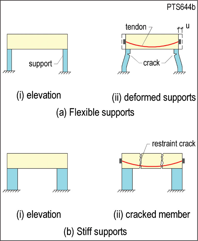
Figure 1. Effects of support restraint on member cracking.
The extent of the restraint cracking in a post-tensioned member depends on several factors including the stiffness of the supports, which is the focus of this article. Figure 1 illustrates two extremes. In Figure 1a, a post-tensioned member on very flexible supports shortens under the pre-compression, forcing the supports to follow the member’s movement. This forced bending can cause cracking in the supports. At the other extreme, in Figure 1b, a member on very stiff supports is prevented from shortening; restraint cracks can develop in the member as it shortens due to shrinkage of the concrete.
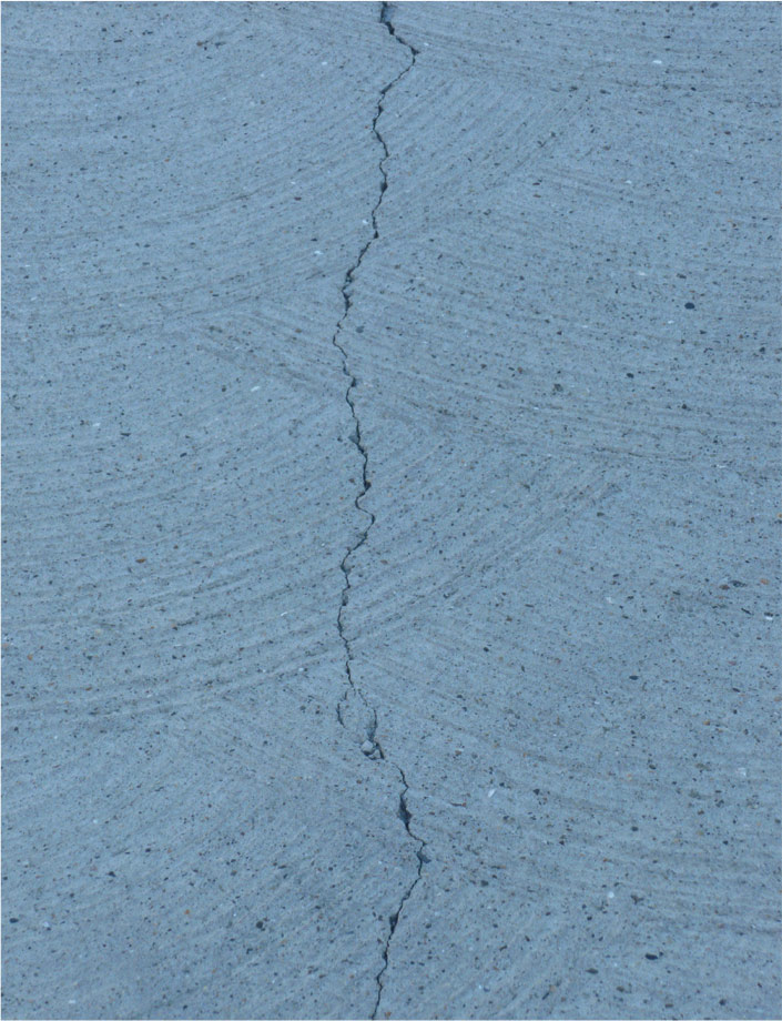
Figure 2. An example of a restraint crack. Cracks typically extend through the depth of the member.
Figure 2 shows a typical restraint crack. Restraint cracks are most pronounced at the first level of a concrete structure, due to the restraint from the foundation. There is less cracking at higher levels. Restraint cracks are often long in comparison to span lengths; they typically extend beyond the length of a panel and through the entire depth of the member. They occur at points of weakness, such as where non-prestressed reinforcement is reduced or terminated, or where there is a reduction in the member’s cross-sectional area.
Experienced design engineers are aware of the possibility of restraint cracking and its consequences. They use a number of measures that allow the post-tensioned member to shorten while minimizing the cracking and its effects in either the member or its supports.
Impact of Support Restraint on Member Strength
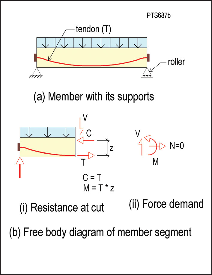
Figure 3. Post-tensioned member with no support restraint to shortening.
Figure 3 illustrates the mechanism by which post-tensioning tendons contribute to the strength of a member when there is no support restraint. This will be contrasted to the case in Figure 4, where the member is subject to support restraint.
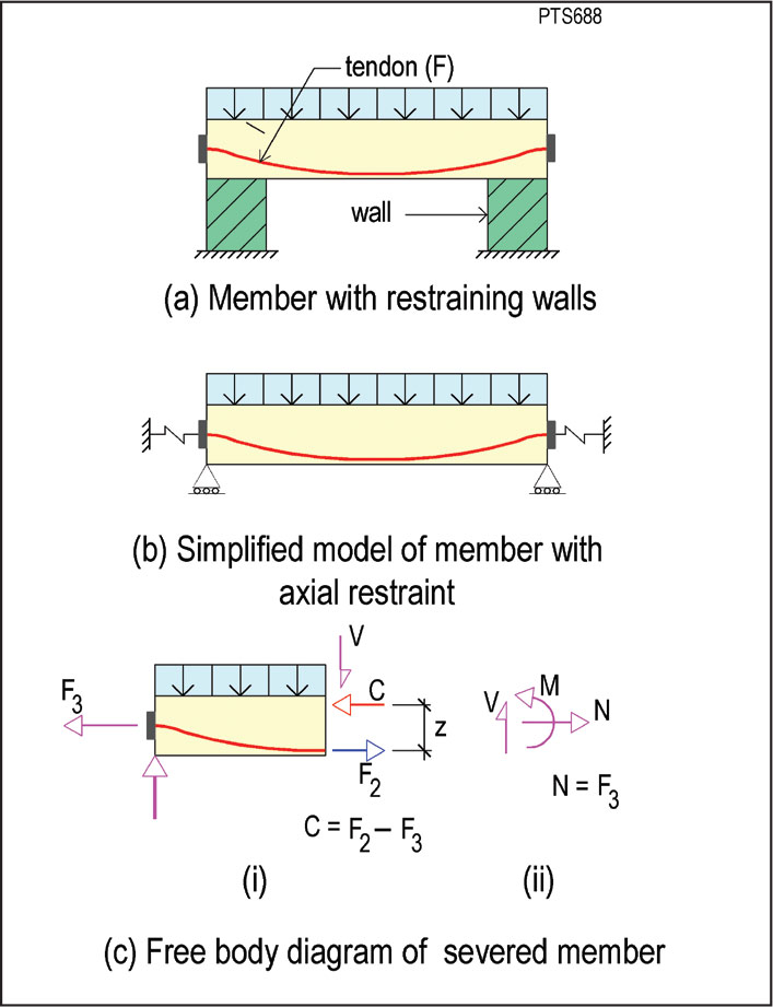
Figure 4. Post-tensioned member with support restraint. F3 is the support restraint, which is modeled with a spring as shown in part (b).
For the member in Figure 3, the strength demand at the cut section shown in Figure 3b consists of the moment (M), shear (V) and axial force (N). The demand actions M, V, and N are in static equilibrium with the forces acting on the segment of the member. For the safety of the structure, the resistance that develops at the face of the cut from the forces T, C, and V should not be less than the demand actions M, V, and N.
Since the member is assumed to be on rollers, the reaction at the support shown in Figure 3b is limited to a vertical force. There are no horizontal restraints at the supports, so there is no horizontal force demand for the cut segment (N = 0 in Figure 3b). The forces developed at the face of the cut must balance the force demand for equilibrium of the segment, namely V, M, and N.
The resistance to the demand moment (M) at the face of the cut is developed by the tendon force (T) and the compression force (C) in the concrete:
T = C Equation 1
M = Tz Equation 2
Where z is the moment arm of the forces at the face of the cut. Because there is no restraint to shortening from the supports, the entire tendon force T is available to resist the demand moment M.
In Figure 4, the member is attached to supports that restrain it from shortening when the tendons are stressed. The following definitions apply to Figure 4 and the remainder of this article:
F = force in the tendon at ultimate limit state (strength condition);
F2 = force in the tendon at service condition;
F3 = restraint of support at service condition.
The member is modeled as shown in Figure 4b with the springs attached to each end of the member representing the restraint of the supports to the shortening of the member. When the tendons are stressed, the supports absorb part of the post-tensioning force, marked F3 in Figure 4c, where the magnitude of F3 depends on the stiffness of the supports. Note that there is a moment at the end of the member due to the shift of the restraining force (F3) at the support from the support/member interface to the centroid of the member, as shown in Figure 4b. However, since this moment is not relevant to the current discussion, it is not shown in the figure.
The procedure followed above for the member in Figure 3 will be used to determine the contribution of the tendon force to the safety of the restrained member. Figure 4c is the free body diagram of the left segment of the member. The demand actions for the equilibrium of the segment are, as before, M, V, and N. In this case, however, from the equilibrium of the forces in the horizontal direction, we have:
N = F3 Equation 3
Thus, in addition to the moment (M) and shear (V), there is a net axial tension (F3) that must be resisted by the actions developed at the face of the cut. Equilibrium of the forces on the segment requires that:
C = F2 – F3 Equation 4
Hence, the resisting moment at the face of the cut is:
M ~ = (F2 – F3)z Equation 5
The approximation sign (~) is used because while the force (F3) actually acts at the interface between the support and the member, it is assumed to act at the centroid of the member for this discussion. The discussion is a simplification of the mechanism for the development of resistance in a post-tensioned member, designed to show the effect of support restraint.
In Figure 4, the force in the tendon under service conditions is shown as F2. With an increase in the applied load, there is an increase in tendon strain, which in turn results in an increase in tendon force. At the ultimate limit state, the force in the tendon is F2 + δF2, where δF2 is the increase in tendon force due to elongation of the tendon. The amount of the increase depends on whether the tendon is bonded or unbonded. For bonded tendons, the increase is localized at the crack and can bring the tendon’s stress to its ultimate strength (fpu). For unbonded tendons, the increase in force is typically considerably less because the increase in strain is distributed along the length of the tendon.
Conclusion
In summary, when a member is restrained at supports, the post-tensioning force available to resist the demand moment (M) is reduced. The magnitude of this reduction depends on the relative stiffness of the restraining supports and the post-tensioned member. The second part of this article, in an upcoming issue, will examine the case of significant support restraint where the entire post-tensioning force is diverted to the supports, leading to restraint cracks.▪