
Part 1: How to Select a Reinforced Concrete Floor System
Vibration analysis has become more commonplace in everyday practice. In office environments, the need for longer spans continues to increase. Open spaces, with minimal or no partitions and no filing cabinets, are becoming even more prevalent (typical electronic office), which translates to less damping to counteract vibrational effects. Amenity centers that include fitness equipment, hospitals, and microelectronic processing facilities are just a few examples of where stringent vibration requirements need to be satisfied for the comfort of building occupants and for the proper functioning of equipment.
Because of their inherent mass and stiffness, reinforced concrete floor systems routinely provide adequate resistance to vibration caused by a variety of sources. Unlike other types of structural framing systems, utilizing reinforced concrete member sizes that satisfy only minimum deflection requirements are more than adequate to satisfy vibration acceptance criteria for walking excitations. For other than walking excitations, the choice of a reinforced concrete floor system may not be obvious. It is important to have sufficient information to select an economical system that satisfies all necessary vibration requirements.
The purpose of this article is to present guidelines to assist design professionals to quickly ascertain when a flat plate system and a wide-module joist system are adequate for various types of vibration excitations. Flat plate voided concrete systems and two-way joists (waffle slabs) will be covered in Part 2.
Sources of Vibration
In general, vibrations can be generated from both internal and external sources. People walking across the floor (walking excitations), people dancing or doing aerobics (rhythmic excitations), and mechanical equipment vibrations are typically classified as internal forms of vibration. Transportation-related sources (such as traffic or trains), construction activities (for example, pile driving), or industrial activities are examples of external sources. The focus here is on internal sources.
Walking excitations are typically modeled as impulsive loads that occur and dissipate very quickly. Heel-drop impacts from a person walking or the impact from a single jump are examples of impulsive loads on a floor system. Periodic loads are caused by rhythmic human activities such as dancing and aerobics or by impactive machinery, whereas harmonic (or equivalently, sinusoidal) loads are commonly used to represent the forces produced by rotating machinery. The vibration source plays an important role in the overall vibration analysis.
Acceptance Criteria
Acceptance criteria for vibration are specified for human comfort and sensitive equipment.
Many criteria have been proposed through the years for human comfort related to vibration of floor systems. However, no universally accepted criteria exist to date. For walking excitations, the peak accelerations recommended by the International Organization for Standardization (ISO) in 1989 have been successfully implemented in a wide variety of situations. For floor vibrations to be acceptable, the peak acceleration of the floor system, which is a function of the floor system’s natural frequency, damping, and effective weight, must be less than or equal to the recommended acceleration, which is equal to 0.5 percent of the acceleration of gravity for office and residential occupancies.
The ISO criteria are also used for rhythmic activities. For dining and dancing and other rhythmic activities (such as aerobics), the recommended accelerations are 1.5 and 5.0 percent, respectively.
The acceptance criteria for sensitive equipment is typically provided by the equipment manufacturers, with regards to limiting vibrational velocities. Vibrational acceptance criteria for sensitive equipment are satisfied for fast, moderate, and slow walking paces when the expected maximum velocity of the floor system (which is related to the natural frequency/stiffness of the floor system) is less than or equal to the limiting velocity given by the manufacturer. The smaller the limiting velocity, the more sensitive the equipment is to vibration. For example, operating rooms in hospitals may require a limiting velocity of 4,000 μin./sec while a facility that manufactures microelectronic equipment may require 130 μin./sec. The microelectronic facility will require a significantly stiffer floor system than the one for the operating room.
Vibration Characteristics
As noted previously, the stiffness of a floor system plays a key role in its ability to combat vibrations. The main component of deflection in a reinforced concrete floor system, which is inversely proportional to stiffness, is from flexure. As such, stiffness can be calculated using the modulus of elasticity of the concrete, Ec´, and the effective moment of inertia, Ie. Because of the transient nature of vibration, the dynamic modulus of elasticity can be used to calculate floor stiffness, which can conservatively be taken as 1.2 times the static modulus given by ACI 318-14 Equation (19.2.2.1.a).
For flat plate systems, Ie´ of a panel section can be calculated based on the average effective moments of inertia of the column and middle strips that make up the panel. ACI Equation (24.2.3.5a) for Ie can be used to determine these quantities for nonprestressed systems; that equation is a function of the cracking moment, Mcr, which in turn is a function of the modulus of rupture, fr. Because of the relatively low reinforcement ratios in flat plates (generally less than 1%), it is recommended to use fr = 4.5λ√f´c instead of fr = 7.5λ√f´c [ACI Equation (19.2.3.1)] to account for shrinkage restraint when determining Mcr. In the equation for fr, λ is the modification factor that reflects the reduced mechanical properties of lightweight concrete and f´c is the specified compressive strength of the concrete.
In the case of wide-module joist systems, the same equation for flat plates can be used to calculate Ie with the exception that Mcr is determined using fr = 7.5λ√f´c. Because of the inherent continuity of wide-module joist systems, ACI Section 24.2.3.6 permits Ie of a joist or beam (girder) to be taken as the average of the values calculated at its critical negative and positive locations.
The effective mass (or weight) of a floor system is required when determining its natural frequency. In general, this quantity is equal to the dead load of the floor system plus any superimposed dead and live loads supported by the floor. When considering the supported live load, it is important to include in the analysis an estimate of the live load that is expected to occur; the code-prescribed live load is only to be used when determining the required reinforcement for the member. For office and residential occupancies, live loads of 11 psf and 6 psf are recommended for vibration analysis, respectively. For all other occupancies, the live load can be taken as zero unless specific information on the actual live load is available.
Damping is a measure of how quickly vibrations subside and eventually stop, and plays a key role in vibration analysis. It is greatly dependent on the nonstructural items that are supported by the floor; for example people, partitions, file cabinets, bookshelves, furniture, and suspended ceilings. The amount of damping in a system is usually expressed as a percentage of the critical damping (a critically damped system is one in which the motion decays without oscillation) and is commonly referred to as the damping ratio, β. Electronic offices and floors with few nonstructural components are usually assigned a value of β equal to 0.02. For office spaces with partial-height partitions, a value of 0.03 is commonly used, while a value of 0.05 would be assigned where full-height partitions are utilized. In the case of rhythmic activity, additional damping is provided by the occupants and β = 0.06 can be used.
The natural frequency, fn, of a floor system, which is related to mass and stiffness, is utilized in all vibration analyses, including checking that applicable acceptance criteria are satisfied. In lieu of performing a finite element analysis, simplified techniques can be utilized to determine fn. In the case of flat plates, the system can be modeled as a thin, isotropic plate, which is free to deflect at any point except the columns. The equation for fn can be found in the STRUCTURE magazine article titled Vibration of Reinforced Concrete Floor Systems, April 2015, by the authors. A simplified equation for wide-module joist systems can be found in the same article. In both cases, the approximate fn are at most 10% less than those from a finite element analysis. These equations can be utilized in the preliminary design stage to quickly ascertain whether the floor system is best suited to satisfy required vibration criteria.
Selecting a System
Parametric studies were performed to determine the conditions under which vibration acceptance criteria were satisfied for flat plate and wide-module joist systems. The following assumptions were used in the analyses:
- Normal weight concrete with f´c = 4,000 psi
- Grade 60 reinforcing bars
- Superimposed dead load = 10 psf
- Live load varies from 40 to 100 psf
- Actual live load from 6 to 11 psf
- Damping ratio = 0.03
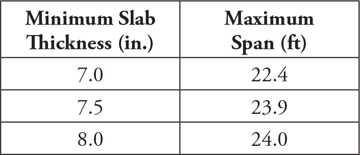
Table 1. Minimum slab thickness/maximum span lengths for flat plate systems subjected to walking excitations.
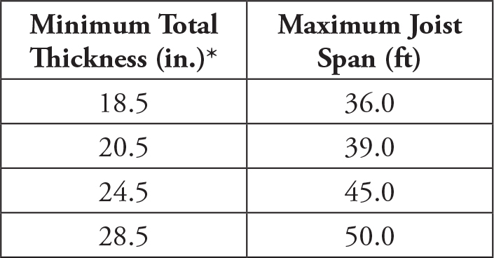
Table 2. Minimum total thickness/maximum span lengths for wide-module joist systems subjected to walking excitations.
For both floor systems, acceptance criteria for walking excitations are easily met. Maximum span lengths that satisfy the acceptance criteria for walking excitations for flat plate systems, as a function of slab thickness, are given in Table 1. A 7-inch-thick slab can satisfy acceptance criteria for walking up to about a 22-foot span; slabs thicker than 7 inches can satisfy the criteria for spans up to 24 feet. Maximum span lengths for wide-module joist systems based on total thickness (4.5-inch slab thickness plus thickness of rib) are given in Table 2. In all cases, the girders can span up to 30 feet. In short, acceptance criteria for walking excitations are satisfied for typical flat plate and wide-module joist systems that meet the minimum requirements for deflection in ACI Tables 8.3.1.1 and 9.3.1.1 for non-prestressed members, respectively.
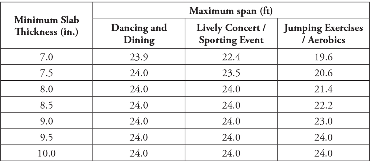
Table 3. Minimum slab thickness/maximum span lengths for flat plate systems subjected to rhythmic excitations.
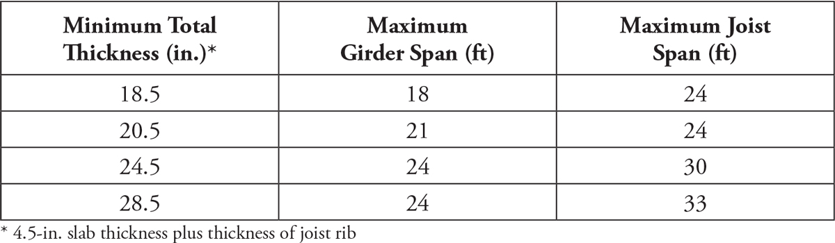
Table 4. Minimum overall thickness/maximum joist span lengths for wide-module joist systems subjected to jumping exercises or aerobics.
Maximum span lengths for flat plate systems based on three types of rhythmic excitations are given in Table 3. Table 4 contains maximum joist and girder spans for wide-module joist systems subjected to jumping exercises and aerobics.
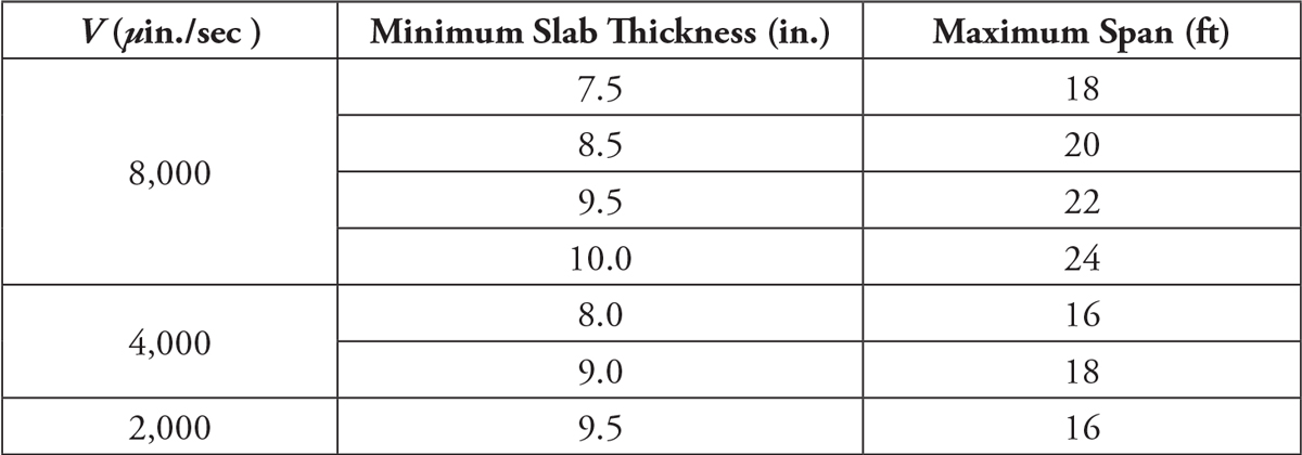
Table 5. Minimum slab thickness/maximum span lengths for flat plate systems as a function of limiting vibrational velocities V.
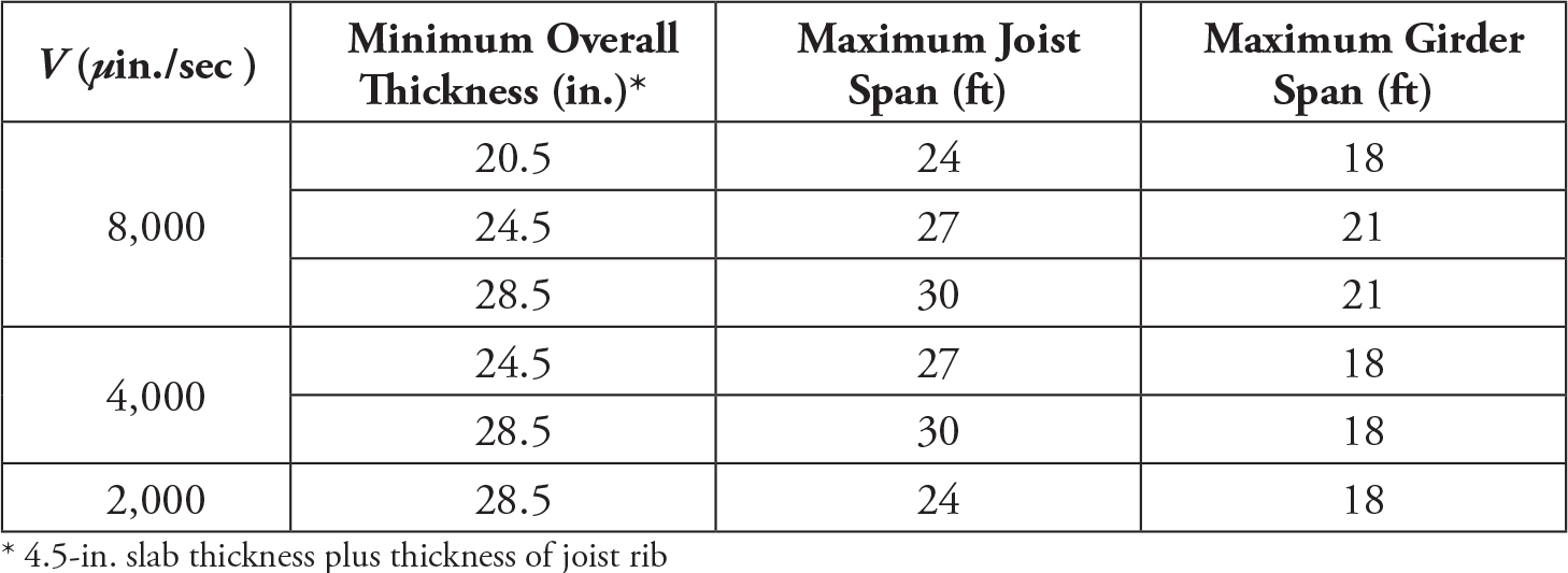
Table 6. Minimum overall thickness/maximum joist span lengths for wide-module joist systems as a function of limiting vibrational velocities V.
Flat plate and wide-module joist systems can typically satisfy the acceptance criteria for sensitive equipment that have limiting vibrational velocities greater than or equal to 2,000 μin./sec. Table 5 contains a summary of the maximum span lengths and required slab thicknesses for flat plate systems assuming a fast walking pace. Given in Table 6 are the maximum span lengths of wide-module joist systems as a function of minimum overall thickness and maximum girder spans with limiting vibrational velocities greater than or equal to 2,000 μin./sec. and a fast walking pace. For vibrational velocities less than 2,000 μin./sec, flat plate and wide-module joist systems will not work for other than slow and moderate walking paces; in such cases, it is recommended to use a stiffer reinforced concrete system.
The information presented in these tables can be used to quickly ascertain whether a flat plate or wide-module joist system is suitable for a given set of constraints. Note that the results from the parametric study are not meant to take the place of a more refined analysis; the main purpose of the study is to provide information that assists the design professional in making a rational decision on a suitable reinforced concrete floor system for vibrations.▪