
Part 2: Mitigate Ponding and Water Intrusion
The author’s company, a forensic engineering and architecture firm, has investigated hundreds of low-slope roof and exterior deck applications with water stains, ponding, framing damage, and structural collapse. The first article, Part 1: ¼ in 12 Design Slope and Water Drainage (STRUCTURE, August 2017), examined two building code parameters that contribute to low-slope roof and deck serviceability issues. This article identifies design and construction practices that limit or prevent free drainage. Potential solutions are presented to mitigate ponding that contributes to serviceability issues and structural framing damage. The goal is to raise awareness in the construction industry of typical practices that may cause harm to structural members and the building envelope.
Background
The 2015 International Building Code (IBC) establishes minimum parameters for building design and construction. A member or system that satisfies applicable individual code parameters may create a less than ideal condition when multiple minimum code parameters are combined. For example, the combination of the ¼-inch per foot design slope and a maximum permitted deflection ratio can create a condition that inhibits free drainage. The IBC, however, does recognize this potential condition in Table 1604.3 footnote “e” and instructs a building designer to investigate applications with insufficient slope or camber for ponding.
Design professionals, contractors, and perhaps code officials have come to believe a roof or exterior deck surface designed to the ¼-inch per foot slope is satisfactory because it meets building code intent. However, member deflection creates an average slope that limits free drainage and contributes to ponding toward the low end. The “average slope” is the slope of a line from the low-end support to the point of maximum deflection for a member. Members optimized to a code-permitted deflection ratio further reduce the average slope and may create a negative slope or a “bowl” condition at the low end that limits or prevents free drainage. The condition is exacerbated for materials susceptible to creep deflection, such as wood. Beam members designed and installed to the ¼-inch per foot slope should be considered a susceptible bay. Readers are encouraged to visit the first article for additional information and potential solutions.
Field observations have identified common design practices that contribute to serviceability issues. These design blunders limit or prevent free drainage and result in unsatisfactory building envelope performance. Additionally, the absence of specific design details and reference to a “best practice” often result in typical construction practices that may meet the general intent of the building code but limit free drainage.
Design Blunders
When design professionals specify framing members to minimum building code parameters alone, it is possible for the constructed roof to have in-service low-slope issues related to ponding or drainage of the system. Five common design blunders that contribute to low-slope issues and potential solutions are summarized below.
Intersecting Planes
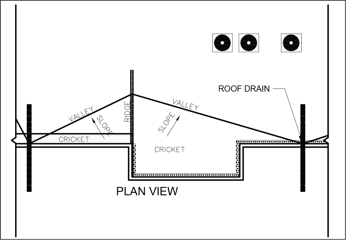
Figure 1. Common minimum roof slope plan with valley.
Building offsets are common and create intersecting planes that contribute to drainage issues for low-slope applications. Design professionals frequently specify the minimum code-permitted slope with little, if any, consideration of the resultant valley slope created by the intersecting planes (Figure 1). Ponding water is commonly observed at valley intersections for low-slope roof and deck (balcony) applications.
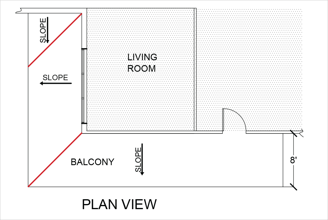
Figure 2. The design slope is reduced at sloped plane intersections.
The diagonal distance between two fixed elevation points is less than the design slope. This principle can be illustrated by two sloped planes that intersect at a right angle (Figure 2). The eight-foot wide balcony with a specified ¼ in 12 slope has a two-inch elevation drop from the wall to the free drainage edge. The diagonal distance denoted in red has the same two-inch elevation change. However, the elevation change occurs over a distance of approximately eleven feet four inches, creating a slope less than the ¼ in 12 minimum slope.
The 2010 edition of the Minimum Design Loads for Buildings and Other Structures (ASCE 7), published by the American Society of Civil Engineers (ASCE) and referenced by IBC, states in part “surfaces with a slope of at least ¼-inch per foot toward points of free drainage need not be considered a susceptible bay.” Therefore, roof and balcony surface areas designed to a ¼ in 12 slope that intentionally direct water to a valley should be considered a susceptible bay. A potential solution is to assign the ¼ in 12 slope to the valley and calculate the associated roof or balcony slope to be shown on the construction documents.
Integrated Columns
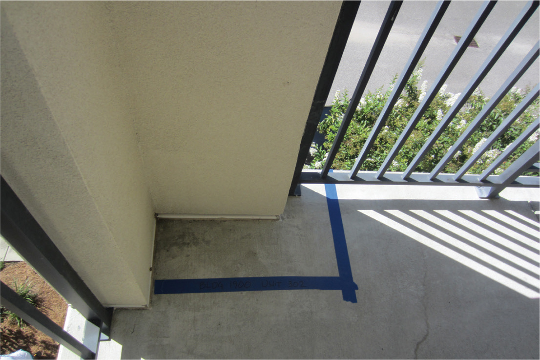
Figure 3. Integrated balcony column without drainage provisions.
Building codes and accepted design practice incorporate “crickets” to divert water for effective drainage. Balcony support columns present conditions that are rarely detailed within the construction documents. Design professionals routinely design integrated exterior balcony columns that serve as “dams” that inhibit water from flowing toward points of free drainage (Figure 3). Columns are frequently located at the balcony perimeter and contain interior edges or corners. Water becomes trapped at the interior edges and often contributes to damage. Design professionals should provide clear details that divert or allow free drainage at these locations throughout the life of the building.
Sloped Concrete Surface
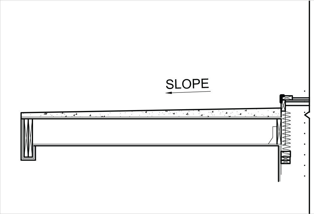
Figure 4. Slope obtained with finish topping.
Many design professionals specify horizontal framing members with a sloped topping surface for drainage (Figure 4). The topping surface is typically a lightweight concrete product installed in a semi-fluid state. Specifications for a “stiff” slump test or to install with a stipulated slope are difficult at best, rarely achieved, and often result in a constructed level surface.
Water percolates the permeable topping surface to the horizontal plane created by the support members. Free drainage rarely occurs since the support member is level or deflected vertically downward, allowing water to pond. Forensic investigations often encounter damage to support members when water finds a breach in the protective membrane between the topping surface and structural framing.
Structural members should be designed and oriented with a positive slope toward points of free drainage for water discharge. The topping surface should conform to the structural member slope to maintain positive drainage. Water that permeates the topping surface encounters the sloped surface and is directed toward the desired free drainage location.
Wood Framing Members
The use of ripped, solid sawn framing members is a common design and construction practice to achieve a desired slope. Lumber grade marks are assigned in accordance with criteria outlined in the code referenced by the American Softwood Lumber Standard (PS 20). The standard specifically states that the remanufacture (ripping) of a graded or grade-marked wood member negates the mark and associated design values of the original product.
The “ripping” of lumber members can be eliminated by modifying the framing detail. One option is to install each end of the lumber member at two distinct elevations to achieve the desired slope. A ceiling joist or furring may be required to obtain a “flat” ceiling. A second option is to specify a truss with the desired top chord slope for drainage and horizontal bottom chord for ceiling attachment.
Another common framing technique orients the framing member perpendicular to the free drainage slope direction. Forensic investigation of this condition typically finds water accumulation toward the center as the member deflects downward. Framing members should be oriented and installed to promote water flow toward points of free drainage.
Differential Deflection
A system of members with the same span are anticipated to deflect a similar amount. Adjacent members with different spans, however, deflect a different amount; the longer span member deflects more, relative to a shorter span member, and creates a “bowl” that retains water.
The Truss Plate Institute (TPI) recognized this phenomenon and identified differential deflection as a design parameter for metal plate connected wood trusses. TPI Section 2.3.2.4 (g) (4) specifically requires the building designer to specify differential deflection design limits. Differential deflections, however, are not limited to wood trusses and this practice should be adopted to other building components. The design professional should consider material properties of the cover, framing, and ceiling when evaluating an acceptable limit to evaluate differential deflections.
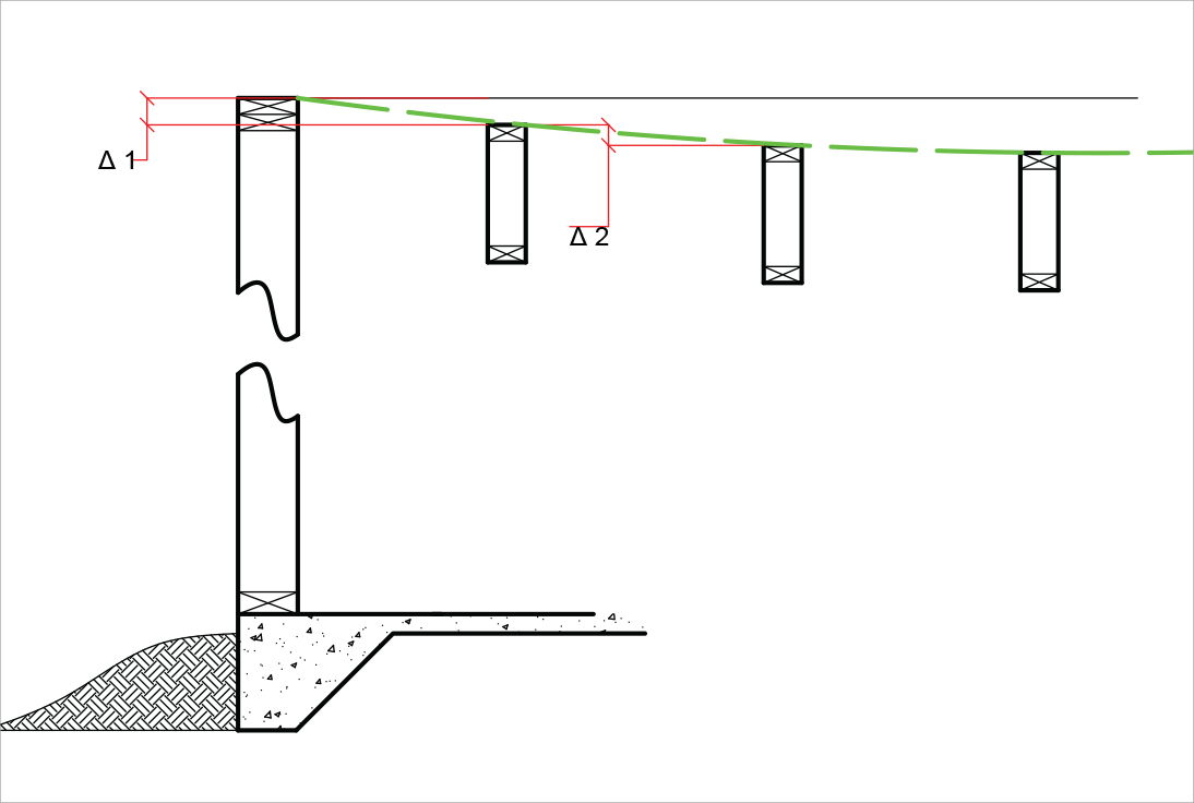
Figure 5. Differential deflection adjacent to wall.
A similar condition exists for structural members installed parallel to a wall supported by a foundation. The design intent is for the wall to be a free drainage location; however, the wall is “rigid” and does not displace downward under load (Figure 5). The structural member adjacent to the wall deflects downward creating a “bowl.” For low-slope members adjacent to a “rigid” member, water may begin to accumulate inward of the intended free drainage point.
Construction Practices
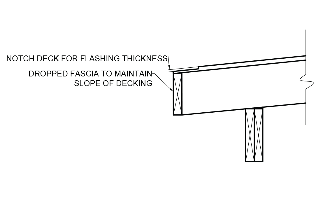
Figure 6. Fascia detail to maintain slope to free drainage edge.
Construction practices also contribute to ponding for minimum slope applications. Fascia members are often installed flush to the top edge of the framing member to create a horizontal surface. Detailed fascia members should be shown “dropped” to maintain the slope of the plane (Figure 6).
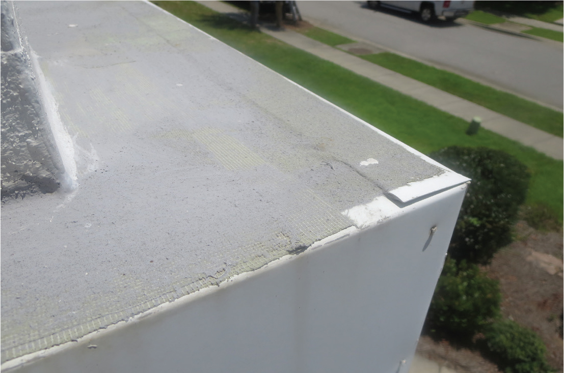
Figure 7. Component thickness prevents free drainage.
Flashing is often installed at the boundary, with one leg placed on top of the roof or deck substrate. The material thickness at the boundary impedes water discharge (Figure 7). The substrate should be notched to receive flashing members and accommodate material thickness.
These are two examples of a common framing practices that may be found within construction standards and implemented in the field. Material installation or thickness impact low-slope drainage and are often neglected at the time of design or during construction. A design professional should recognize the limits of building code requirements, standard details or practices; In these cases, it is important to provide “best practice” details within the construction documents to mitigate potential ponding and serviceability issues.
Conclusion
Accepted design and framing practices often contribute to serviceability issues with low-slope roof and deck applications. Practices or conditions that inhibit or prevent the flow of water toward free drainage should be identified during the design phase and changed.
Design professionals have the ability to create in-service conditions that diminish ponding and promote free drainage. Slopes should be increased to maintain a sufficient slope to drain at intersecting planes. Framing members should provide the drainage plane and not rely completely on the slope of the topping or finish surface. Additionally, differential deflection of adjacent structural members should be investigated and the appropriate limit assigned to mitigate low areas for water retention.
Framing practices and standard construction details often create high points that inhibit water drainage in low-slope applications. The design professional is encouraged to detail boundary conditions to promote drainage.▪
References
International Building Code, 2015 Edition, International Code Council, Washington, DC.
American Society of Civil Engineers Minimum Design Loads for Buildings and Other Structures (ASCE/SEI 7-10), ASCE, Reston, VA.
American Softwood Lumber Standard (PS 20-05), National Institute of Standards and Technology, Washington, DC.
National Design Standard for Metal Plate Connected Wood Truss Construction (ANSI/TPI 1-2014), Truss Plate Institute, Alexandria, VA.