
Part 2: Right Way, Wrong Way with Software
Last month’s article (Structural Analysis, STRUCTURE, July 2017) was devoted entirely to model generation, the critical first step in an accurate analysis and design using the Finite Element Method (FEM). Remember, FEM is broken up into three basic steps:
- Modeling: A pre-processing step where a user defines elements, connectivity, support conditions, and forces that represent various loading conditions.
- Analysis: Processing step that requires little user input – the user establishes a few important parameters, and the software solves a vast set of equations based on the model.
- Validation and Design: Post-processing; the step of interpreting and verifying the results of the analysis and then designing elements based on parameters determined by the material codes one uses.
In this article, the modeling is completed by considering loads on the model, followed by a discussion of Steps 2 and 3.
Loading and Load Generators
Once the model is created, and the nodes and elements are defined, loads must be imposed on the structure. Self-weight dead load can be automatically generated. Other gravity loads are typically defined by manual input. However, wind and seismic forces can be applied to the model using load generators that are available in many programs. The user simply defines code criteria based on the building’s location and the software determines the load parameters, computes loads, and imposes those on the structure based on the geometric information the program ascertains from the modeled elements.
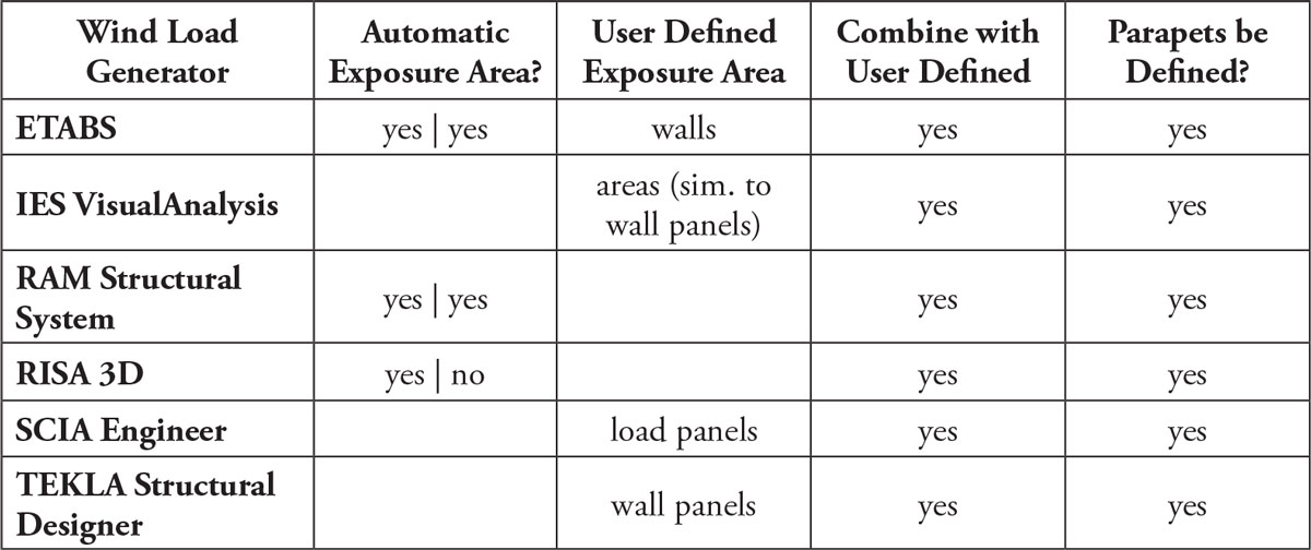
Table 1. Wind generators.
Wind load generators (Table 1) generally use deck (or slab) edge information to determine overall floor dimensions. Together with the story height, the program can determine the area for the wind load to be applied. Programs are becoming increasingly precise in the method of defining exposure areas by utilizing wall panels (load panels). Wall panels can be used for automatically generated pressures, resulting in a more precise method for applying wind loads. Utilizing wall panels is a practice best used when dealing with semi-rigid diaphragms since pressure can be added to windward walls, leeward walls, side walls, and roofs.
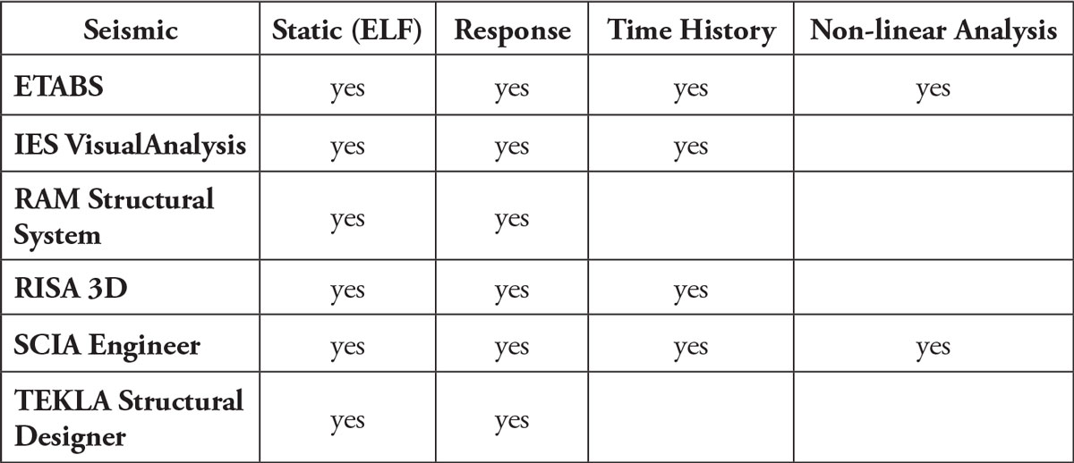
Table 2. Seismic generators.
Seismic load generators are more complicated, as they can either be based on equivalent lateral force procedures (static load) or dynamic analyses such as response spectrum analysis, time history analysis, or a non-linear dynamic analysis (Table 2). Model stiffness is very important to seismic load determination and dynamic behavior of the model, and it is imperative to model stiffness as accurately as possible. Similarly, the mass of the model is a very important element in determining the dynamic properties, and much care should be used in defining the dynamic mass. It is likely users are conservative and model dead loads are higher than the actual loads on the structure; thus, dead load is not always the same as the mass that should be used in determining dynamic properties. An arbitrarily high mass leads to a lower frequency and a higher building fundamental period; this may result in a lower seismic force coefficient depending on the structural system. Much more can be said about the importance of accurately modeling mass, stiffness, and dynamic characteristics relative to seismic demands. However, that is a broad discussion that will have to be examined in future articles.
Whether seismic or wind lateral loads are determined, the applied force from the load generator will either be a single load applied to the entire building diaphragm, or a distributed load applied to the edges of the diaphragm (common for wind) or over the entire area of the diaphragm (common for seismic). Users often have the option of single or distributed forces when generating the loads and must consider the type of diaphragm before making the selection. When using a rigid diaphragm, either option of loading will have the same result. Conversely, when a semi-rigid or no diaphragm is modeled, the only option for loading is distributed loading. For example, a single load on a semi-rigid diaphragm leads to incorrect load distribution to lateral framing members, and diaphragm stresses and deflections that are completely erroneous.
Considering all of the above, the most overused feature of software programs today may be the simple load generator that only works effectively for simple models. Features that are common in present-day buildings, such as sloped or stepped floors or roofs, sloped walls, re-entrant corners (floor perimeters that jog in/out), and non-uniform mass loading, can quickly invalidate the generated load. Sometimes these nuances can be accounted for, and the generated loads can be used, but other times users simply need to put away the automatic load-generating features and compute and define loads manually. Look at it this way – you have two options:
- Manually determine the loads for a structure using software with good element modeling features that accurately represent the real structure, or
- Automatically generate loads using software having poor element modeling features that are not an accurate representation of the real structure.
Most engineers would choose Option 1. Using software that can accurately determine the vertical and lateral load distribution through an indeterminate structure with potentially semi-rigid diaphragms, element stiffness modification factors, and pinned or fixed-end conditions, all the way down to fixed, spring, or pinned supports to represent foundations, are much more valuable. Choose software programs by their ability to create an accurate model and analyze complex sets of equations, not for load generation features that will quickly become invalid with minor complexities of the structure.
Model Analysis – Processing
The analysis step of the finite element method is mostly the software “crunching the numbers” and very little is done manually by the user. A user needs to pay attention to a few general setting options that affect the model and are typically located under analysis or processing menus in the program. An example of these settings is auto-meshing, discussed in Part 1; wherein a finer mesh often provides better accuracy of elastic behavior. Also, plate/shell elements are more accurate as square shapes, and finer meshes increase the likelihood that the elements are square or nearly square. This is especially true in complex models. However, one should consider the adequate convergence of the solution; that is, if the limited increase in accuracy of the model using a more refined mesh outweighs the processing speed needed to achieve those results. In general, the recommended maximum element mesh size would be the span distance divided by ten and the minimum plate size should be no less than the thickness of the element being modeled. Of course, these are guidelines that must be re-evaluated for unique situations.
Other settings to be considered for analysis or processing pertain to P-delta effects. The P-delta effect accounts for the fact that gravity loads increase lateral deformations, increasing element shears and moments, and adds to the overturning moment of the building, becoming an important feature in the overall structural performance, its lateral instability, and in element design. In the first few iterations of the lateral analysis of a building, it is possible that considering P-delta effects will lead to an unstable structure. Therefore, member sizes may need to be refined through an iterative process without the P-delta effect included until reasonable sizes are determined, and a stiffer structure is established. In all cases, the option to consider P-delta in the analysis should be revisited once initial sizes are determined.
Validation and Design
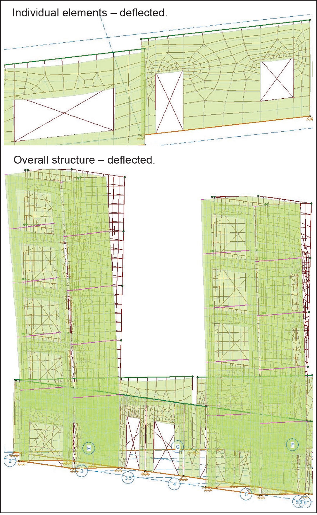
Animate deflected shape for overall and individual elements to confirm results.
Once the modeling is complete and the analysis has been performed, it is then time to turn to the final step of the finite element method – validation and design. With each different material, different design codes require checks based on the forces and stresses in the elements of the structure. However, before applying design code rules to the structure, it is first important to have confidence in the results.
An important aspect of validation and design is reviewing the data to determine whether modeling and analysis gave expected results. The initial step in this review can be checking the nodal reactions in comparison with the applied loads on the structure. This may seem like an elementary check, but it is very important. Often errors occur when users assume their loads are applied in a manner in which the program is not meant to be used. In addition to load generation errors, another example would be whether self-weight is automatically calculated and applied, and, if it is applied, whether it is applied to dead loads and/or effective mass. Other examples of loading errors can occur when modeling openings in floors and walls of plate/shell elements. When programs perform auto-meshing routines and remove plate/shell elements where the opening occurs, the program also removes the load that would have been applied to that area. This, of course, leads to unconservative results. There are very few programs that account for this missing load automatically, so the user must often address this manually.
Another great method to review the validity of the results, which is less quantitative and more qualitative, would be to animate deflection results of the lateral load cases and load combinations. The ability to amplify the results can help in determining whether the structure is behaving as anticipated, or if there is something new that was not expected. At times, the unexpected animation is due to a modeling error that can quickly be observed and repaired. In more complicated structures, however, the modeling approach may need to be changed. When observing the animation, there is an opportunity to understand which element is more critical than expected, how to improve lateral efficiency, where to increase the stiffness of a single element or multiple elements, or whether to add a new lateral frame in a particular area of the structure.
Furthermore, it is vital to verify the analysis results before performing code checks. If code checks are performed too early, there could be an over-emphasis on getting the model to simply pass code. During this rush to circumvent the process and not verify analysis results, a critical aspect or underlying problem with the structure may be missed. Unfortunately, the results of these scenarios are all too common. It is important to resist the temptation of a combined “analysis and design.” Be sure to separate them into distinct steps in the process.
Once there is confidence in the analysis results, then the process of design and code checking may begin. Take time to review the software’s implementation of the code provisions to understand and agree with the design process; only then should the program be used to design and check the demand (analysis results) versus element capacity as defined by the code. As mentioned earlier, this is the appropriate time to apply conservative measures based on engineering judgment.
Finally, have the finite element method checked by a colleague with strong experience with the method. All of the steps – modeling, analysis and validation, and design – should be verified. In today’s structural engineering firms, a quality review process should be as focused on the finite element software programs as it is with the drawings that the company sends out.
Conclusion
It is very important that all engineers in an organization truly understand the software tools used within the company. Recognize the balance between idealized, simple modeling that saves time (and budget) and more complex modeling that may be a better representation of the actual building. This takes a thorough understanding of building elements and more time to implement into the model. At each step on the path of modeling, analyzing, and designing, answer the question: does this item provide an accurate representation of reality to provide a safe, efficient, and effective design or is it compromising? There was a time, before finite element methods and software tools became available, when there was little choice but to over-simplify a design problem. Today, however, many software tools are readily available, and an FEM solution should be considered for all substantial structures. When using these tools, ensure the model accurately represents structures by examining beyond basic idealized settings. There is a point of diminishing returns when more complex modeling yields the same design solution, a good point to approach in modeling.
Also, junior engineers are generally the savviest with software and are typically the ones creating the models, analyzing, and designing. They are the doers within most companies. However, senior engineers – some of whom rarely use software products – are the ones doing the reviews and the quality control checks of the projects produced by the office. Unfortunately, these quality assurance measures are often based mostly or entirely on manual calculations, report reviews, and drawing reviews. Senior engineers need to be well versed in the software tools to review the models as well, so younger engineers are not left alone in the process of creating, analyzing, verifying, and designing. Also, this responsibility to understand software may be expanded beyond junior and senior engineers to the engineering project managers and business owners. How can someone manage design teams, create expectations, define deliverables, and manage the risks to organizations without understanding the tools that are becoming critical to completing design tasks for many or all of the projects that go through engineering firms?
Utilize these software tools for lateral analysis and continue to progress in understanding, maximizing their responsible use. Remember to always uphold the integrity of structural engineering by accurately modeling, analyzing, reviewing results, and designing with software. As the author, C.S. Lewis, states,
“We all want progress. But progress means getting nearer to the place where you want to be. And if you have taken a wrong turn, then to go forward does not get you any nearer. If you are on the wrong road, progress means doing an about-turn and walking back to the right road; in that case, the man who turns back soonest is the most progressive man.”
It is essential to continue to make progress with the use of software. If at any point the profession becomes overly reliant on software for the wrong reasons or realize software is being used without truly understanding both the capabilities and the limitations, then structural engineers may have to go back and learn – or re-learn – until what software can do is fully grasped. C.S. Lewis also said, “It is not your business to succeed, but to do right.” Moreover, by doing right, success will follow. Do right and build these models for lateral analysis with integrity, by modeling and analyzing structures to represent the real structure accurately, and providing safe and reliable designs for building owners and occupants.▪