
Structural engineers occupy a unique position in building design in that they are the sole resource for most of the information that is critical to the building cladding design. The Structural Engineer of Record (SEOR) is responsible for designing the lateral and gravity force resisting systems of buildings to perform within certain code prescribed seismic (and wind) drift limits. They also provide the design for roof and floor spandrel elements (for multi-story buildings) to perform within specific deflection criteria, based on the exterior cladding system and function.
The proper design of the building enclosure – often by a Specialty Structural Engineer (SSE) – cannot be performed without two specific and clearly defined structural criteria: story drift and spandrel deflections. Project documents should specifically identify real (calculated) building displacements, not just regurgitated code limits. For instance, in a very stiff shear wall system, seismic drift displacements may be a fraction of the code prescribed limits. There is an unnecessary cost impact to the project if only the code limits are defined. Real (calculated) displacements are best, which should include torsional displacements of the floor and roof diaphragms, where they occur.
Slab Edge/Spandrel Deflections
Spandrel beam deflections require careful consideration. Live load deflections of spandrel beams should be based on something other than a proportional span limit, like L/360 or L/600. It is best to provide a specific deflection amount based on the performance expectations of the cladding system. For example, assume a 30-foot, simple span spandrel beam supporting one floor of exterior enclosure framing in a multi-story building. The default rule of thumb of L/360 would produce a deflection of 1 inch. If the dynamic horizontal joint between floors is a sealed joint using a material that has a warrantable movement potential of 50% (silicone or urethane), then the actual joint size would want to be at least 2 inches. That is 2 inches for only the prescribed live load beam deflection.
In addition to live load deflections, the joint must also allow for superimposed loads added after the exterior wall system is installed, as well as thermal-gradient-driven volumetric changes in the cladding materials, long-term volumetric changes, and creep. A joint larger than 2 inches is a very big joint. A much more visually acceptable joint would be ½- to ¾-inch, which would require the spandrel live load deflections to be less than ¼- or 3⁄8-inch, respectively, regardless of span length. For the same 30-foot simple span spandrel beam, a deflection limit of 3⁄8-inch would be L/960, much stiffer than the rule of thumb would prescribe.
It would be best to move away from proportional span deflection limits in relation to spandrel framing and the associated cladding design and move toward a rational, realistic stiffness or deflection criteria based on aesthetics and performance.
The real expectations of the spandrel stiffness and cladding implications should be discussed with the architect and owner early in the design stages of a project.
Joint Sizing
All foreseeable deflections should be cataloged by the SEOR to determine the proper joint sizes in the exterior cladding systems. For example, for concrete construction, long-term shrinkage and creep should be identified, not only for the slab edge or spandrel elements but the vertical load bearing system – columns or walls – as well. All contributors to floor shortening should be identified. For post-tensioned floors, the floor plate shrinks over time, reducing both the width and breadth of the building. Composite construction
spandrel beams (concrete deck carried by steel beams linked together via shear studs) will “creep” due to the shrinkage and creep of the topping concrete, even though there is a steel beam present. The creep effects of composite construction are frequently overlooked in domestic (U.S.) practice.
If vertical or horizontal joints in the cladding system are not sized properly, the exterior cladding can be forced to resist axial loads until failures or yielding occurs. If the cladding material includes brick or other clay-based materials, long term irreversible volumetric expansion should be identified. Brick absorbs environmental moisture and increases in size, after it is first cooled from the firing process, throughout its service life.
It is generally accepted that the building jointing system should function and remain as an uncompromised weather barrier before, during, and after lateral displacement of the building in response to wind and seismic forces that generate an elastic response of the lateral force resisting system. It is also generally accepted that once the building’s lateral force resisting system enters the energy dissipation mode of inelastic behavior, it is acceptable for the cladding system to breach the weather barrier capacity while avoiding damaging contact and the potential of creating falling hazards. Most performance testing of wall systems demands compliance to this protocol. This two-stage performance design concept should be discussed with the owner/developer during the early design phases of the project.
In-Plane Forces
In-plane forces imparted to or generated within the cladding system must be considered. The cladding system must be designed to resist those “internal” forces. The effects of the in-plane shear and any overturning moments that may be induced in a wall panel should be resolved and developed into the building superstructure. In-plane lateral seismic forces for tall, narrow elements, like column covers, may increase vertical shear demand on the stud support fastenings several times greater than the shear gravity load demand alone, especially for heavy cladding materials.
Multi-Story Walls
All buildings drift when resisting lateral forces due to wind or seismic events. Buildings that utilize moment frames for the LFRS tend to drift the most, and member sizes in the LFR frames are often controlled by drift limits/lateral displacement restrictions rather than strength. If exterior walls are multiple stories tall, bypassing the floors, and intended to remain rectilinear during their service life, then the accumulated drift over the multiple floors must be accounted for in the connecting hardware and the interface with other finishes, for example where the roofing membrane bridges across the shear plane at the back of the parapet. Accumulated drift may be more than 8 inches for a 3-story wall. There is some debate as to whether one should algebraically sum the drifts at multiple floors or take some reduction to account for the real phenomenon that all floors do not experience their maximum drift simultaneously. This is especially true where a higher mode of vibration controls the generation of the seismic forces. Either way, accumulation of drift should not be ignored where wall systems are continuous across multiple floors.
Building Corners and Seismic (Story) Drift
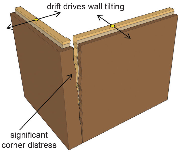
Figure 1a. With no joint provided at the corner, when walls tilt out of plumb – driven by upper level story drift – the corner wall will fail.
Almost all buildings have corners where adjacent exterior walls converge. Dealing with exterior cladding wall corners is a challenge due to the bi-directional movement required – movement parallel to each of the two orthogonal sides of the building that meet at the corner. Often, the issues of the corners are ignored and the two intersecting walls do not have any accommodation for bi-directional drift. This means that the corner area will most likely fail during the inelastic lateral displacement of the building (Figure 1a). If the cladding material is heavy, such as stone or brick, then significant hazards may exist without proper corner detailing.
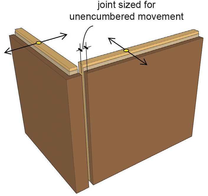
Figure 1b. A joint of sufficient size each wall to
tilt unencumbered when driven by upper level
story drift.
The simplest approach to resolving bi-directional movement at the building corners is to terminate one wall or the other at, or very near, the corner and provide a vertical dynamic joint of sufficient size to allow for the full drift movement of each wall without a clash of the cladding materials (Figure 1b). This may create a very large joint that is difficult to seal.
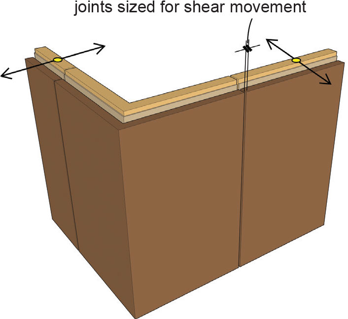
Figure 1c. Rigid “L” corner with minimal width joint (shearing action, not extension and compression). “L” corner needs sufficient bracing and stiffness.
A third option is to move the joints away from the corner and frame the “L” shaped corner element as a rigid unit braced to the floor below. Smaller joints can be used as they function primarily in a “shearing” mode (Figure 1c).
Keep in mind, all exterior framing joint scenarios have interior finish ramifications. The interior finishes are largely outside the purview of the SEOR and/or the SSE, but a valued team partner would direct some discussion toward those issues so that they can be discussed during the development of the design.
The more options that are available to resolve corner challenges, the more valuable the services of the engineer become.
Other Situations of Note
Openings in floors adjacent to the exterior wall, such as for stairs, mechanical shafts, and elevator shafts, can create challenges. The supporting slab edge may be nonexistent. Interruptions in the typical exterior wall framing scheme create challenges for continuity of dynamic joints and, specifically, story drift joints. Stairs, in particular, often require framing at intermediate levels (for the landings) that can be difficult to resolve if the support of the studs shift half a floor up or down.
Stacking single story walls that are tied to each floor, but bear on each other without a horizontal deflection joint, can create unintended load bearing walls which are not designed to carry floor loads. The stacked walls are much stiffer than the deflecting spandrel beam, and the floor loads tend to follow the stiffest load path until something fails.
Vertical steps in continuous horizontal drift joints should be avoided wherever possible. Whenever a vertical transition occurs, the width of the vertical portion of the joint at the transition must resolve the story drift movement without inducing a clash. This may be several inches in moderate to high seismic zones.
Framing at or near egress doors and openings can be a challenge. If a wall deforms in-plane (racking, for instance) and causes egress doors to bind and become non-functional due to poor detailing, then the required means to evacuate the building may be compromised.
Avoidance of Clashes
When detailing cladding joints to accommodate building movements, the designer is required to interpret and apply the appropriate code provisions. For example, ASCE 7-10, Chapter 12.12.3, uses the terms “structure” and “structural(ly)” when defining certain performance issues relative to separations and damaging contact. These terms may lead one to think along the lines of “primary structure,” but that may be an incorrect interpretation of the intent of the code. Here is what the code says (ASCE 7-10; bold added for emphasis):
12.12.3 Structural Separation
“All portions of the structure shall be designed and constructed to act as an integral unit in resisting seismic forces unless separated structurally by a distance sufficient to avoid damaging contact as set forth in this section. Separations shall allow for the maximum inelastic response displacement (δM). δM shall be determined at critical locations with consideration for translational and torsional displacements, where applicable, using the following equation: δM =Cd*δmax/Ie (Eqn. 12.12-1) Where δmax = maximum elastic displacement at the critical location.”
Adjacent structures on the same property shall be separated by at least δMT, determined as follows: δMT = (δM12 + δM22)½(Eqn. 12.12-2) where δM1 and δM2 are the maximum inelastic response displacements of the adjacent structures at their adjacent edges.
Where a structure adjoins a property line not common to a public way, the structure shall be set back from the property line by at least the displacement δM of that structure.”
Examine the last paragraph. It is logical to assume that the reason a “structure” should be set back from the property line by the amount of the calculated inelastic drift is so that, under the code prescribed circumstances, the “structure” doesn’t sway across the property line and crash into adjacent buildings or other constructions. It can be interpreted that the term “structure” in this usage means “building,” not “primary structure.” It makes little sense to allow appurtenances, overhangs, awnings, canopies, cornices, and other architectural projections to cross the property lines and create clashes with adjacent constructions. If the reason for the set back is, in fact, clash avoidance, then the “structure” is anything and everything attached to the “entity” we call a complete building. Borrowing from the first line of the quoted text, “all portions of the structure” would appear to mean everything attached to the building.
The first paragraph of the quoted code text above appears to require the building to function “without damaging contact” for “all portions of the structure” at separation joints. Joint separations allow for maximum inelastic response displacement. If the intent of the code were solely focused on avoiding “structural” damage, then it would be satisfactory for architectural features such as fins, cornices, windows, canopies, and awnings to crash together and create falling hazards, preserving solely the “primary structure.” One can reasonably deduce that falling hazards are precisely what the code is intending to preclude and separations should be sufficient to avoid damaging contact (clashes) with any and all portions of the building.
For lightweight cladding (EIFS, wood, and perhaps stucco,) the consequences of damaging contact are not nearly as severe as damaging contact of dimensional stone slabs, brick veneer, or even CMU or manufactured concrete or stone veneer. However, damaging contact is just that – damaging contact – which is required to be avoided by code.
Picture yourself sitting on the witness stand in a trial where someone got hurt due to falling debris. Consider, would your design decisions regarding building separation or the width of the dynamic joints be appropriate? How would the lay person in the jury interpret “all portions of the structure” knowing the code’s main purpose is to protect life safety? Does the code mean only the structural elements are to avoid damaging contact? If in doubt, it would be prudent for the local building official having jurisdiction over the project to make an official informed and considered interpretation of the intent of the code.
Conclusion
During the process of developing the design of a building, the SEOR and/or SSR should, to the best of their abilities, catalog and clearly convey all foreseeable building movements for the cladding designer’s use. It is also important to inform the client of the necessities of proper jointing in the exterior cladding system for the cladding system to accommodate all relevant building movements. In some cases, the primary structural elements can be made stiffer (extra cost) to reduce displacement, and reduce joint sizes (reducing joint cost). However, more commonly, the cost-benefit ratio of changing the structure versus changing the joint width drives the solution to the cladding joints.
Wide joints may be maintenance challenges, so smaller joints may be preferred. However, small joints must function to allow for the necessary building movements while avoiding clashes with cladding materials and creating public safety hazards from falling debris. For a complete, thorough design, in-plane forces in the cladding system must be resolved via a complete load path to the supporting elements.
Cladding design can be every bit as challenging, in some circumstances, as the design of the primary structure. It should be approached as an important, necessary, and integral part of a complete building system.▪