
Structural engineers are primarily concerned with the design and assessment of load bearing structures. Of paramount interest is ensuring sufficient structural capacity (strength) to withstand the loads (demand). It is also important, in an increasingly energy-conscious world, not to waste material unnecessarily. In the design of reinforced concrete (RC) slabs, the engineer may use limit analysis to assess the flexural strength of a design but, until recently, this has involved a laborious hand calculation using either the yield line technique or the strip method. Modern limit analysis tools that automate these approaches are now available and were presented in the September 2015 edition of STRUCTURE magazine (Modern Limit Analysis Tools for Reinforced Concrete Slabs, Ramsay et.al). Regarding the assessment of RC slabs, the two approaches are equally efficient at capturing accurate collapse loads. However, when it comes to design, the lower bound approach offered through the equilibrium finite element (EFE) software provides a distinct advantage in that, in addition to providing a safe prediction of the collapse load, the load path taking the loads to the supports is available through principal moment trajectories. With a knowledge of the load path, the engineer can tailor the reinforcement layout and size to minimize material usage. This article presents a simple, but common example where using this approach reduced the reinforcement requirement by 50%.
The Importance of Equilibrium
In the design or assessment of simple structural members, the practicing engineer can utilize an extensive library of strength of material solutions offering known theoretically exact solutions to problems where the geometry, material, boundary, and loading conditions are simple. With more complex structural forms, the theoretical solution is unknown, and the engineer must use numerical simulation techniques, such as the finite element (FE) method, to achieve an approximation of the solution.
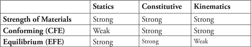
Table of conditions satisfied weakly or strongly for ‘pure’ finite element formulations.
The FE method produces stresses/moments that approximate the theoretical solution, and the solution normally converges with mesh refinement. The nature of the approximation is dependent on the FE formulation adopted, as indicated in the Table where pure FE formulations, i.e., ones that satisfy the constitutive relations exactly and only weaken one of the other essential conditions, are considered.
Commercial FE systems usually use a conforming (CFE) formulation that weakens equilibrium conditions at the expense of strong compatibility. This runs counter to what the practicing engineer requires, as stated by Edward Wilson: Equilibrium is Essential – Compatibility is Optional. http://bit.ly/2qJFWrN
Equilibrium is essential because, if the FE stresses are not in strong equilibrium with the applied loads, the engineer cannot be certain that his/her reinforcement is sufficient to withstand the applied loads. This statement is derived from the lower bound theorem of plasticity, which is nicely expressed as:
The only reason why structural designers sleep soundly is the second [lower bound] theorem of plasticity theory. This theorem says that no matter how I designed my structures, they are safe because everything was in equilibrium, nowhere [were] the stresses …too large, and I used ductile components and joints. (From the CIE4150 Plastic Analysis of Structures course description, Delft University of Technology, Netherlands) http://bit.ly/2rsvJx3.
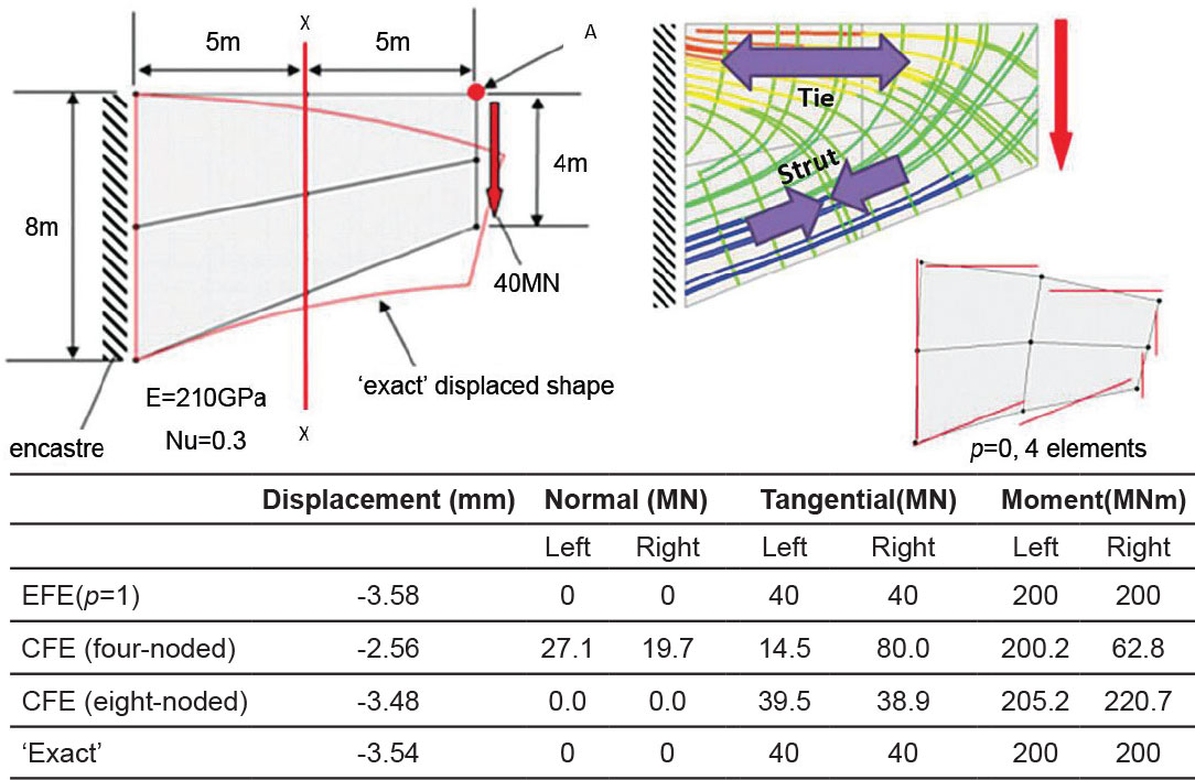
Figure 1. Tapered cantilever problem (linear elastic).
With CFE models, the engineer may not appeal to the lower bound theorem unless he/she is sure that the model is sufficiently refined to provide a decent approximation to a strong equilibrium solution. The EFE formulation, on the other hand, does provide solutions that, even for the coarsest mesh, offer the practicing engineer a strong equilibrium solution with which a safe design may be determined. The tapered cantilever problem of Figure 1 demonstrates these ideas by comparing sectional stress results from coarse CFE and EFE models.
The CFE elements, which, respectively, can approximate constant and linear stress fields for the four and eight noded elements, recover continuous displacements (and hence strain/displacement compatibility) at the expense of strong equilibrium. The equilibrium element satisfies equilibrium exactly at the expense of strong compatibility, as illustrated by the discontinuous edge displacements shown for the constant stress field element (p=0). The displacements from the equilibrium element model are, however, rather accurate in an average sense, as shown in Figure 1’s accompanying table (vertical displacement at point A), and are more than adequate for assessment of serviceability conditions such as that of maximum displacement.
The exact stress results on the section are easily determined from statics. The FE stresses for both formulations are discontinuous across the section. For the CFE model, this leads to different stress results on either side of the section, neither of which are in equilibrium with the applied load. With the EFE model, however, even though the stresses may be discontinuous, the sections are equal and opposite, and, most importantly, are in equilibrium with the applied load.
Figure 1 also shows a plot of principal stress trajectories from the EFE model. These form an orthogonal net of lines and provide information about the direction and magnitude (color) of the principal stresses at a point. Such trajectories clearly show the way in which the force is transmitted from the applied loads to the supports. Because equilibrium is always satisfied, they do not change significantly with mesh refinement. Principal stress trajectories may be used to guide strut and tie representations so that the reinforcement is optimized in terms of layout and size.

Figure 2. Constant torsional moment field in an RC slab.
In addition to linear elastic analysis, EFE may be used to conduct limit analysis to determine the plastic limit load. In contrast to the yield line technique, which is an upper bound technique providing potentially unsafe predictions of the collapse load, EFE provides lower bound solutions which are safe. The constant torsional moment field shown in Figure 2 provides a simple example of these ideas. This moment field would be observed in a square slab supported on three corners and with a point load at the fourth corner.
The principal moments are determined from Mohr’s circle. The principal moment trajectories are shown as red (hogging) and blue (sagging) lines. This problem was adopted by the IStructE and used in the magazine Structural Engineer as an “And Finally …” question in the August 2016 edition.
The constant torsional moment field is transformed into principal moments (principal moment trajectories are shown in Figure 2). The trajectories cross the slab at 45 degrees, with hogging trajectories shown in red and sagging trajectories in blue. The magnitude of the principal moments is identical everywhere in the slab. Whereas such a slab might be reinforced with an orthogonal mesh placed both in the top and bottom and parallel to the sides of the slab, it is evident from the principal moment trajectories that an optimal form of reinforcement would require it to be placed parallel to the trajectories. Further, it is seen that, rather than reinforcing both the top and bottom in two orthogonal directions, only one direction is truly required. Thus, a knowledge of the moment field within the slab leads to a potential reduction in reinforcement steel of 50%!
Principal moment trajectories provide a total picture of the statics within the slab from which an optimum form of reinforcement may be easily established. This is considered, in the example problem below, for a more common slab configuration where the moment fields are more complex.
A Slab Design Problem
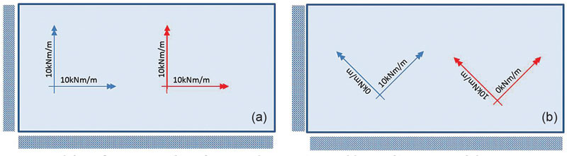
Figure 3. Slab configuration and reinforcement layouts; a) Initial layout, b) ‘Optimized’ layout.
The reinforcement for the 2- by 1-meter rectangular slab, simply supported on two adjacent sides and with a 25kPa uniform load, as shown in Figure 3, is to be designed. The approach adopted will be design-by-assessment; i.e., a reinforcement layout will be assumed, an assessment performed, and simple scaling of reinforcement size applied to ensure that it can safely carry the load.
EFE will be used for the design but, since this slab possesses no known theoretical solution, the yield line technique will first be used to establish an upper bound to the collapse load. This will be used to verify the EFE solution.
While highly efficient commercial software is now available for yield line analysis, a more conventional approach will be demonstrated in this example. This is because it mimics the more traditional hand approach where likely collapse mechanisms are sought and then geometrically optimized to find the lowest upper bound solution.
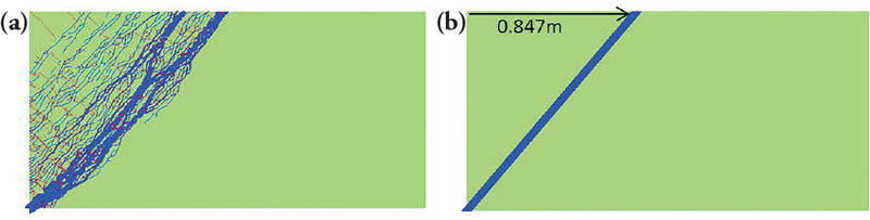
Figure 4. Upper bound (yield line) solutions; a) Refined unstructured mesh (30kPa), b) Coarse optimized mesh (23.61kPa).
Yield line analysis based on a finite element analysis of a refined unstructured mesh of triangular elements provides a good, although fuzzy, image of the collapse mechanism, as seen in Figure 4a. This indicates that the collapse mechanism can be idealized as a single sagging (blue) yield line angled across the slab and initiating at the supported corner. A coarse mesh including this mechanism is then constructed and the optimum termination position of the yield line, along the long free edge, is determined by geometric optimization. Since the yield line analysis provides an upper bound approximation, the position giving the lowest collapse load is taken as the optimum position.
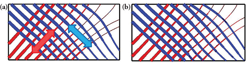
Figure 5. Lower bound solutions showing principal moment trajectories and collapse loads; a) Initial layout (23.59kPa), b) Optimized layout (23.30kPa).
The lower bound solution from EFE, based on a relatively coarse mesh, is shown in Figure 5a and a very tight bound on the collapse load is provided, thus verifying the solution when compared to the yield line solution.
If the safe collapse load provided by EFE is taken, then the collapse load is just under the required 25kPa. The reinforcement size would need to be increased slightly to account for this. Having achieved a safe design that is not overly conservative, the engineer could stop at this point with the knowledge that he/she has done a sound job. If, however, the engineer wants to whittle down the cost of the slab, then further work is required.
The principal moment trajectories of Figure 5a may be interpreted as an optimal reinforcement layout and sizing. It is evident from this diagram that, similar to the case of the constant torsional moment configuration, by the simple expedient of rotating the reinforcement layout through 45 degrees and removing the rebars that serve no function, a reduction in reinforcement of 50% might be achieved. This has been confirmed using EFE, and the result is presented in Figure 5b. The principal moment trajectories are virtually unchanged, as is the predicted collapse load which is reduced by a little over 1%.
Practical Conclusions
This article has demonstrated how, using an appropriate software tool, e.g. EFE, that offers up a complete and easily understandable graphical representation of the statics within a slab through principal moment trajectories, the practicing engineer can safely make very significant material/cost savings in the design of an RC slab.
This article has not considered the serviceability limit state (SLS) conditions of deflection and cracking. However, these could be considered separately and the reinforcement requirement to satisfy these conditions added as further, separate layers of reinforcement.
The equilibrium finite element formulation is not a new one, dating back as it does to the early days of finite element research. However, Equilibrium Finite Element Formulations, published by Wiley, March 2017, has resolved many of the numerical issues that were initially an obstacle to the acceptance of the method. http://bit.ly/2qObMyL
EFE, as currently formulated, is for the assessment of slabs but it may be used, as demonstrated, for slab design through a design-by-assessment approach. It is possible also to formulate EFE as a true design tool where the reinforcement layout becomes a variable in the process. This formulation of EFE is a future development that is being considered by the authors.▪