
On May 27, 2016, Navy Pier unveiled Centennial Wheel, the much anticipated 525-ton Ferris wheel erected in celebration of the Pier’s 100th year. Both tourists and Chicago natives alike had been anxiously awaiting the reimagined landmark, which stands an impressive 50 feet taller and weighs nearly twice as much as its predecessor.
Planning for Centennial Wheel began almost two and a half years before its 2016 Memorial Day opening. Structural engineering firm Thornton Tomasetti (TT) worked closely with Navy Pier to select a Ferris wheel that not only offered an impressive guest experience but also would fit within the structural limitations of the iconic Pier. After all, the wheel was to be constructed on the roof of an operating parking garage atop a 100-year-old pier stretching half a mile into Lake Michigan.
Due in large part to the engineering restrictions inherent in this project, Chicago-based James McHugh Construction Co. (McHugh) started planning for the project more than one year prior to the former wheel’s September 2015 demolition. McHugh engaged Simpson Gumpertz & Heger (SGH) to assist in the evaluation of construction picks and crane placements, crucial elements to ensuring the project’s safe and timely completion. SGH also provided shoring and repair design during construction.
Existing Structure
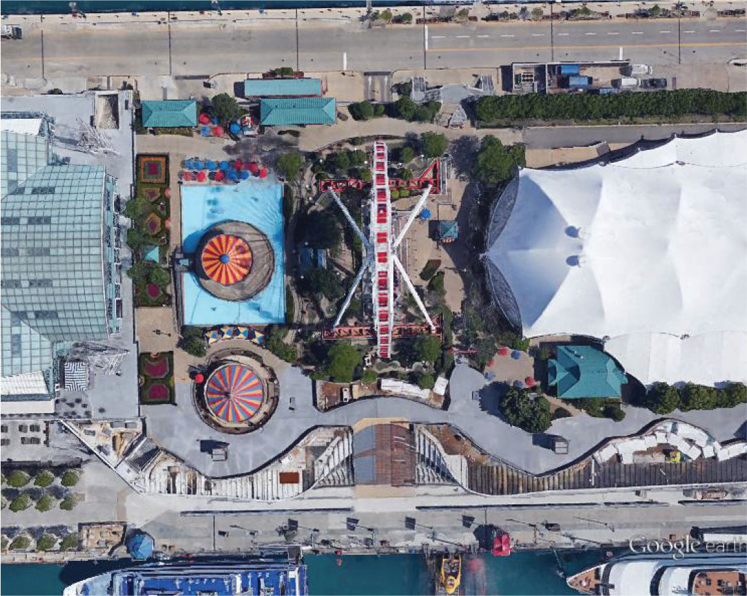
Figure 1. Pier Park at Navy Pier. Courtesy Google Earth©.
Navy Pier was constructed in 1916 on thousands of 12-inch diameter wood piles. In 1992, this portion of Navy Pier was redeveloped with a precast concrete parking structure supported on concrete caissons spaced at 60 feet in the north/south direction, with 30-foot bays in the east/west direction and a full-width expansion joint east of the original wheel. The upper Pier Park level of Navy Pier houses the main public space which includes the Ferris wheel, swings, carousel, and other amusements, as shown in Figure 1.
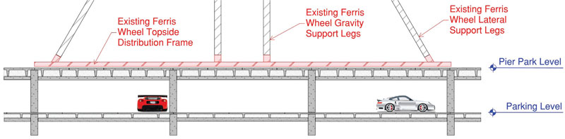
Figure 2. East-west pier cross section.
The structural framing of the upper Pier Park level consists primarily of 7.5-foot-wide by 40-inch-deep precast concrete double-tees supported by precast concrete inverted tees and columns. The lower parking level consists of similar concrete framing. However, the lower level utilizes 12-foot-wide by 26-inch-deep double-tees due to the lower load carrying capacity necessary for car parking. Figure 2 depicts a cross section of the pier with the original Ferris wheel.
In the original design, the superimposed dead load on the park area varied between 120 and 360 pounds-per-square-foot (psf) for trees and landscaping, with a design live load of 100 psf for the public spaces. A service drive on the north side of the deck, shown above the wheel in Figure 1, accommodated 250 psf.
Ferris Wheel Selection
Eight legs supported the original Ferris wheel, all of which landed short of the north/south column grid. A 6-foot-tall, topside steel distribution frame atop the precast structure, shown in Figures 1 and 2, was utilized to transfer design loads to the underlying columns. The new design sought to eliminate this steel framing so riders could board at Pier Park level without traversing unsightly ramps.
Five different Ferris wheels were initially considered. TT reviewed the gravity and lateral loads imposed on the existing structure, as well as how each wheel’s attachment points interfaced with the Pier structure. The support points for each wheel were overlaid on the existing precast structure. Navy Pier sought to minimize the structural depth at the Pier Park level, the impact of a new structure on drive aisles and parking spots in the garage below, and the number of new foundations required. This meant the closer the support legs were to the east/west girder lines, the better.
Ultimately, TT recommended the DW-60 by Vekoma/Dutch Wheels of the Netherlands, designers of the former Ferris wheel. Six legs support the new wheel; two parallel legs on each side of the wheel, and two legs that angle east to support lateral loads. Its 120-foot horizontal spread most closely aligned with the existing structural grid.
Structural Design
Gravity loads were provided directly by the wheel designer, but TT had to identify code-required environmental loads, namely wind and ice loads. The team met with the City of Chicago plan examiner early on to address code interpretation, which resulted in the use of ASCE 7-05 to better capture the combined effect of wind blowing on members with ice build-up. The basic lateral wind force was approximately 250 kips. The team estimated 1.25-inch thick ice build-up around all of the wheel lattice members – an additional weight of more than 200 tons, 40 percent of the wheel’s self-weight. The additional sail area from this build-up resulted in an increase in the lateral force of 65 kips in one direction.
A new structural support system was required to transfer load from the wheel’s six legs to the foundations. Gravity support was provided by two new 18-inch-thick concrete walls installed in the parking garage directly below the four main legs of the wheel. Each leg supports approximately 600 kips. These walls encase the existing precast columns and engage the existing caisson foundations directly below. The walls were designed as deep beams, using the strut and tie method, with eight 290 kip-per-square-inch DYWIDAG bars for the main tie force.
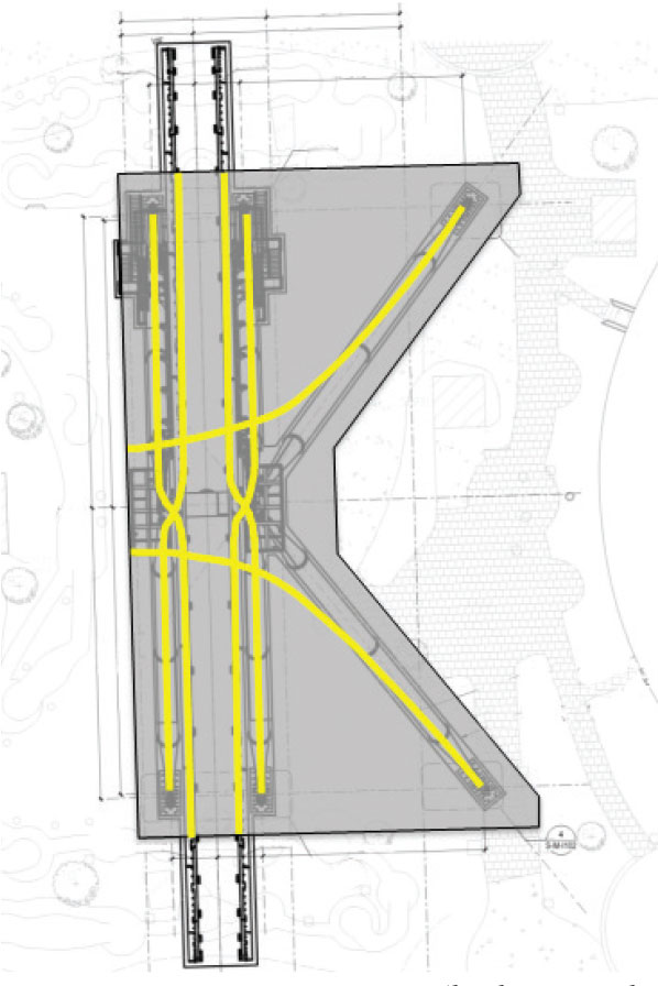
Figure 3. New concrete mat (high-strength tendons shown in yellow).
The lateral load from wind is resisted by the splayed legs, which are supported by new, reinforced concrete columns located in the parking garage atop micropiles that extend another 120 feet to bedrock. Each micropile can resist 100 kips of pullout. The horizontal in-plane reactions that occur at the base of each leg exceed the existing structure’s diaphragm capacity; therefore, a new 14-inch-thick concrete mat was designed as a tension tie between the splayed legs and main legs. High-strength tendons stressed to 150 kips were used to pre-compress the tie mat (Figure 3). Since the splayed legs extend over the existing expansion joint, a slip detail was specified to allow the mat to slide over the adjacent structure to an independent support on isolated columns.
There was some concern about shrinkage in the mat and placement of the anchor bolts. If the 120-foot mat spread was continuously poured, the concrete shrinkage could have pulled the anchors more than one inch out of position. The wheel manufacturer required a very tight tolerance of five-thirty-seconds of an inch. Therefore, the design and construction team divided the concrete installation into two pours. The first pour was centered around the anchorage locations and the second pour, which infilled between the first, followed after two days of curing to minimize the net movement of the anchor bolts due to shrinkage.
Another challenge emerged during the transfer of load from the wheel legs into the structure, which required the installation of twenty 42-millimeter anchor bolts. Supplemental reinforcing, in accordance with ACI 318 Appendix D – Anchoring to Concrete, was specified at each location to prevent concrete breakout. The team utilized 3-D modeling of reinforcing steel, anchors, and plates in the congested base shoe areas, which drove decisions simplifying rebar layout for constructability.
Construction
Before construction of the Centennial Wheel could begin, McHugh was tasked with dismantling the existing wheel. Several rigging contractors were consulted, and Advantage Industrial Systems (AIS) ultimately was selected to join the team that would work alongside Vekoma to complete this unique project. SGH was asked to evaluate the ability of the existing structure to support the applied construction loading. Available original erection drawings, precast shop drawings, and design calculations were reviewed to determine existing structural member strength. Independent calculations confirmed the strength of the existing structural framing.
At the start of construction, SGH performed a condition assessment of the existing Pier structure. Observations of structural components were limited to the underside due to the existing waterproofing membrane. Isolated locations of deterioration were identified around previous deck penetrations, and SGH provided McHugh repair drawings to address the observed double tee flange distress.
The new Centennial Wheel is not only erected on top of Navy Pier, but also on the roof of the west parking garage. McHugh and SGH worked closely to ascertain material storage locations, construction staging, and crane selection for both dismantling the existing wheel and erecting the new wheel. SGH analyzed the existing structure in consideration of the anticipated sequences, material and equipment staging, crane locations, and construction loadings. Components of the existing and new Ferris wheel were transported to and from the site by truck via the service drive on the north end of the Pier Park level. The maximum individual component weight was the new wheel’s axle at 48,000 pounds.
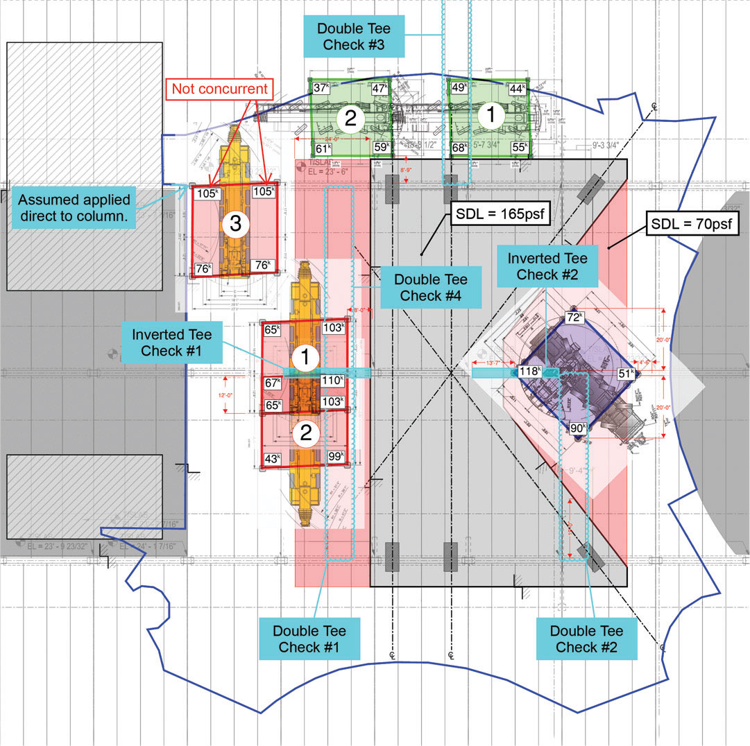
Figure 4. Crane outrigger reactions and member checks.
McHugh worked with Royal Crane Services and Imperial Crane Services to optimize equipment selections to facilitate the necessary lifting. Crane outriggers were placed on heavy timber cribbing to distribute the load to the supporting members. The maximum anticipated crane/outrigger load was 70 kips during dismantling and 118 kips during erection. A summary figure from the construction load analysis is shown in Figure 4, taken from the delegated design submittal. The figure shows the three cranes used during installation (red, blue, and green), the various locations as they moved during the installation process, and the maximum anticipated outrigger reactions. While the double-tee framing is similar throughout, several member checks were performed due to the various combinations of uniform superimposed load and outrigger point loading. Preferred crane/outrigger placement was over the columns or inverted tees. When locating them on those components was not possible, SGH analyzed the load distribution based on the stiffness of the timber cribbing and the supporting double tees. A parametric study determined the distribution of load between the six double stems below the timber cribbing, and shear demands often dictated permissible crane outrigger locations.
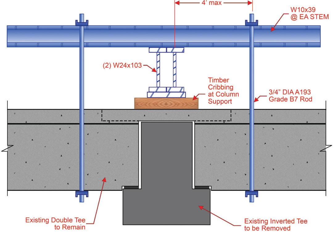
Figure 5. Shoring to complete installation of new structural support.
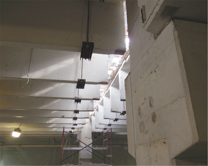
Figure 6. Installed shoring from below.
Before erection of the new wheel could commence, McHugh installed the new structural support system which required removing an existing precast concrete inverted-tee beam and replacing it with a concrete wall. Shoring of the double-tee beams on the upper Pier Park level was required to remove the inverted-tees. The dead load of the upper Pier Park level framing is approximately 100 psf; the design live load of the lower parking level framing was 50 psf. Accordingly, the analysis determined the lower parking level of Navy Pier was inadequate to support the shoring loads from the level above unless engaging approximately twice the tributary width. SGH developed a shoring solution that consisted of hanging the precast concrete members from steel beams temporarily installed above the upper Pier level, shown in Figures 5 and 6. The new support walls are depicted in Figure 7.
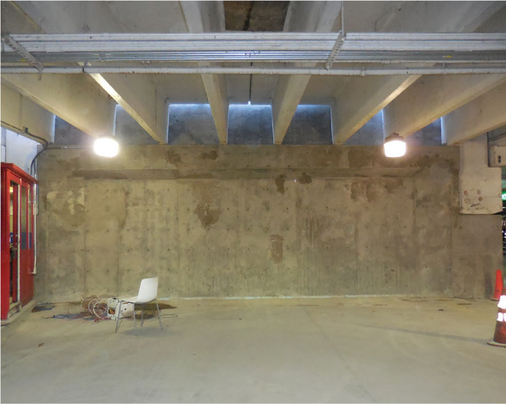
Figure 7. New Ferris wheel support walls.
Construction on Centennial Wheel began in late October 2015. Months before the start of construction, in partnership with Navy Pier and the Pier’s tenants, McHugh selected two consecutive days to close the Pier to erect the largest elements of Centennial Wheel. Five cranes totaling 1.2 million pounds of lifting capacity were used during assembly.
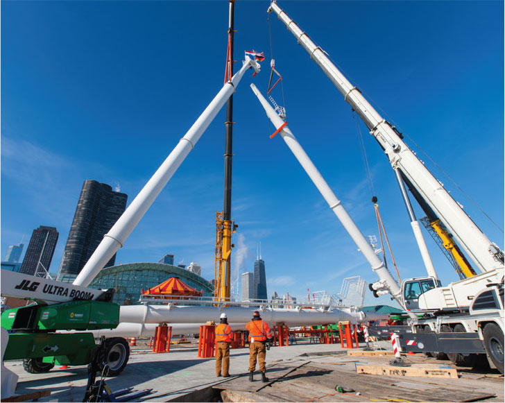
Figure 8. First set of gravity legs just prior to establishing a connection.
The wheel was erected by bolting two of the gravity support legs to the base shoe, standing the legs up, and forcing a large diameter pin into the top connection (Figure 8). These two legs remained unstable until a lateral support leg was installed. The main picks were accomplished utilizing two 250-ton cranes and one 100-ton crane operating in unison, instead of what otherwise would have been a single 500-ton crane for a more “typical” job. The center axle, the heaviest crane load installed on the Pier, weighed 48 kips, requiring a critical outrigger reaction (Figure 9). The spokes and rim of the wheel were incrementally installed in a clockwise motion, and passenger cabs were connected in groups of three on opposite sides of the wheel to maintain balance.
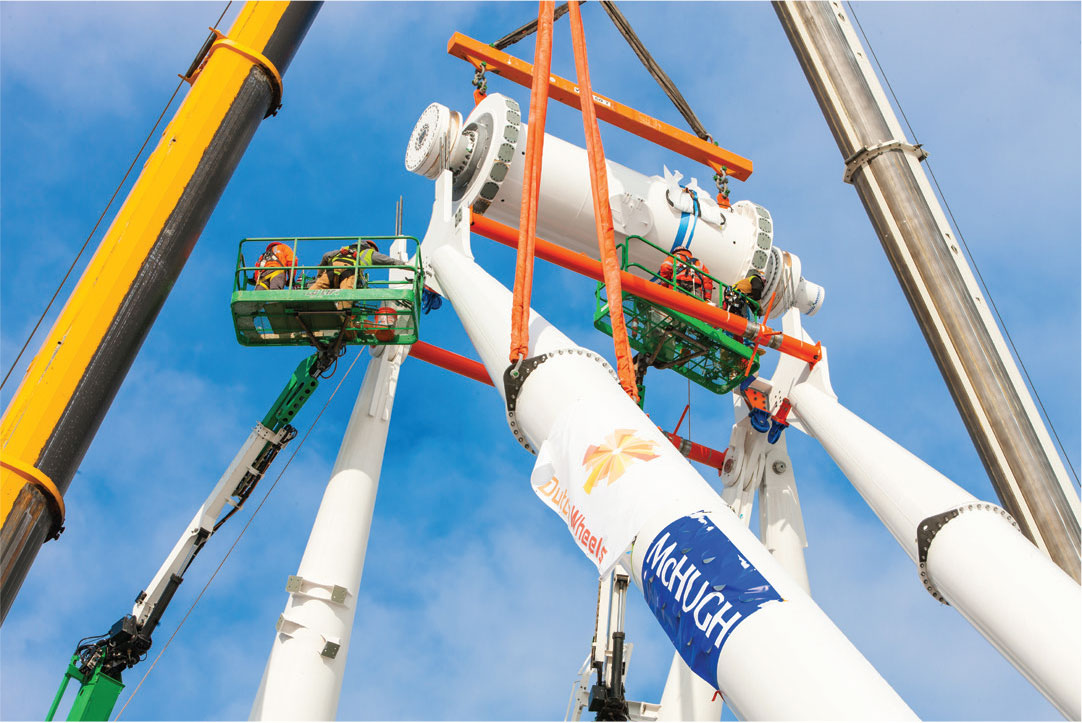
Figure 9. Installation of the axle.
There was nothing typical or standard about the construction of Centennial Wheel. On the first day of Pier closures, the high temperature in Chicago was only 9° F. The following day was only slightly better with a high of 15° F. With most other job sites across the city closed down, the Centennial Wheel construction team worked 16-hour days.
Centennial Wheel opened in May 2016 to record crowds. While visitors may be most impressed by the new temperature-controlled gondolas, in-cabin video screens, and better views, the Chicago-based teams behind the wheel know the real accomplishment is in the engineering details: a 525-ton, 196-foot-high structure constructed over a fully-functional parking garage on a pier by more than 500 men and women in roughly 25,000 hours. Now, that is impressive.▪
Project Team
Owner: Navy Pier Inc., Chicago, IL
Structural Engineers of Record: Thornton Tomasetti, Chicago, IL (Design), Simpson Gumpertz & Heger, Chicago, IL (Construction)
Contractors: Primary – James McHugh Construction Co., Chicago, IL
Specialty – Advantage Industrial Systems, LLC, Frankfort, IL
Architect of Record: James Corner Field Operations, New York, NY / Gensler, Chicago, IL
Fabricators: Vekoma Rides Manufacturing BV, The Netherlands