
Port Bolivar Ferry Maintenance Operations Facility
The Texas Department of Transportation (TxDOT), Houston District, has provided ferry service across Galveston Bay on SH 87 between Galveston Island and the Bolivar Peninsula for over 80 years. This free service represents the only means of public transportation across the Bay. Every year, millions of people, automobiles, and cargo are moved via this ferry route. The 2.7-mile trip takes approximately 18 minutes, saving motorists at least an hour of commute time on alternate local roads north of the Bay. This transportation link is also critical to the residents of Bolivar Peninsula. When a storm threatens, it serves as the quickest and primary means of evacuation through Galveston to the causeway and the mainland.
The ferry service fleet presently has six ferries. Each ferry has a six-member crew and can carry approximately 500 passengers and 70 vehicles. During the non-peak season, at least three vessels set out from the ferry landings from any given side across the waterway on 30- to 60-minute schedules, daily. During the peak season, additional ferries are used at more frequent intervals. Until 2011, TXDOT operated five ferries and four work docks at its Ferry Maintenance Facility. When a sixth ferry was added to its fleet, and since at least one ferry operates a 24-hour schedule, TxDOT recognized the need to expand and enhance the Facility, including the provision for a fifth work dock.
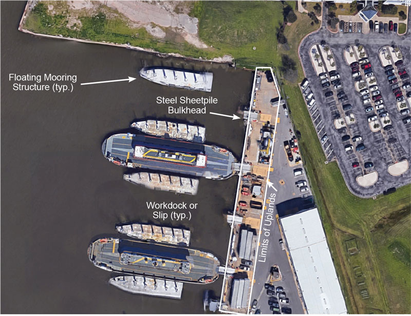
Figure 1. Panoramic view of Maintenance Facility. Courtesy Google Maps©.
In June 2014, TxDOT contracted with Lockwood, Andrews & Newnam, Inc. to perform engineering inspections and condition assessments of both waterside and uplands elements at the Facility, including the bulkhead system, berthing and mooring structures, the bilge containment tank, approach ramps, and other ancillary structures. Mechanical and electrical equipment, dredging requirements, distressed concrete-paved uplands, and storm water conveyance were also evaluated. An aerial view of the site is shown in Figure 1. A Preliminary Engineering Report (PER) described the findings and recommendations for repairs or replacement of various engineering elements and systems required to restore the overall function, integrity, and serviceability of the Facility. Subsequently, a contract was awarded to Lockwood, Andrews & Newnam to perform detailed engineering designs and prepare the construction documents for the redesigned Facility.
Constraints on Design
The design team faced many challenges, including environmental, financial, functional, and operational considerations. One of the key engineering challenges was to develop the new five-slip layout within the defined limits of the property to avoid any encroachment into the Port Bolivar-Galveston Ferry waterway route, other nearby vessel holding areas to the south, and the U.S. Army Corps of Engineers’ compound that is located to the north. This, in turn, influenced the landside space programming needs for utilities, dock equipment, and other machinery that support each work dock. The overall design solution also had to meet the strict requirements for permitting approval, and the structures had to be designed to withstand the effects of wave action, current, and wind events.
Secondly, considering TxDOT’s annual budget allocation limitations and its mandate to have at least two of the existing work docks remain fully operational during construction, the design accommodated up to four phases into other sections of the existing older structures that will be in use during construction. After reviewing different iterations for constructing the new works while keeping the Facility opened, it was determined that this approach would create the least disruption to TxDOT’s ongoing daily ferry operations.
The addition of the fifth work dock to moor a fifth ferry year-round was paramount to TxDOT’s plans. Currently, the ferries are each moored against a floating, rectangular dock. Each occupies about 200 feet by 60 feet of water space. The presence of these large mooring units complicated the redesigned configuration. How could an additional work dock be accommodated in a limited area of water surface already near capacity in terms of existing infrastructure?
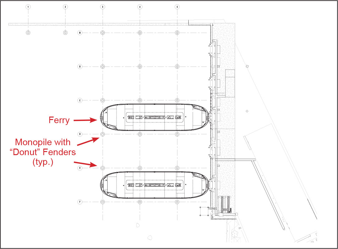
Figure 2. Structural site plan – new workdocks configuration.
Using a combination of creative design concepts, technical analyses, and a series of manipulations of the ferries to generate the most favorable layout, it was concluded that the existing mooring units should be replaced with a monopile system, without floating docks. The ferries will continue to berth end-on. The use of a monopile system created an additional 90 feet of usable water space with the new berth configuration (Figure 2).
This solution will serve three separate functions. Firstly, each monopile will serve as a “guide-in” dolphin as a ferry approaches the work dock, then as a berthing structure when a ferry is brought to rest at any of the work docks, and finally as a mooring structure for securing a ferry while it is in the dock.
Design Criteria
Unlike other fields of civil engineering, there are few standards and no established codes that govern the design of port and harbor berthing and mooring structures. Furthermore, it is well established that the design solutions for these types of structures are a function of facility type and location. For example, the redesign of the TxDOT Facility considered factors such as site bathymetry, geotechnical consideration, vessel characteristics, facility expansion constraints, currents, storm surge, hurricane-induced wind and wave loads, berthing and mooring loads, and utility requirements. The berthing and mooring sequences, and other ferry maintenance-related activities, were observed over multiple weeks to gather information to fully understand TxDOT’s operational needs. Engineers also used this information to help identify potential conflicts during construction and for operational safety considerations.
Waterside Design
It is difficult to predict or calculate the maximum environmental forces on these types of maritime structures during their service lives given the unpredictability of wind and wave intensities and directions, the presence of currents, and even the load status (ballasted or loaded, etc.) of the ferries while they are moored. Therefore, reasonable estimates of extreme environmental conditions were used to direct the design of each element or component. However, what about the combined effects of the environmental loads on the ferries and on the structures that restrain them?
Although as much as 21 feet of storm surge was recorded during the Hurricane Ike storm event, the design team assumed a design wave height of 15 feet as a reasonable criterion because the site is considered to be sheltered from the effects of strong currents. Also, large wave forces that are generated from either passing ships or wind-induced wave action, and the presence of the continuous bulkhead wall along the length of the property, means that the incident waves are reflected. Given the facility’s configuration and the selected waterside structure types, these wave force effects were considered to be of lesser intensity to those that are generated from direct wind and current forces and therefore did not control the structural design.
For maritime structures, wind forces are based on an industry-standard 30-second design wind velocity as recommended by the World Association for Waterborne Transport Infrastructure (PIANC). This time interval is necessary to allow fender compression or the full tension in mooring lines to develop, respectively. For this project, the design wind speed was estimated from the ASCE-7 intensity maps and adjusted using a wind duration correction factor relative to the 3-second gust.
Modified versions of the velocity pressure equation were used to calculate the forces due to currents and wind. The modified equations account for the design ferry’s shape and its side and underwater projected areas, the effect of shielding from other moored ferries and obstructions, and the orientation of the ferry relative to the flow of the fluids. Wind and current loads were computed assuming various angles of attack between 0 degrees on the bow and 180 degrees on the stern of a ferry. The concurrent wind and current forces acting directly on the structures were also determined.
For mooring purposes, two limiting wind speeds from any direction were established: less than 60 mph winds of 30-second gusts during dock operations and a 130 mph survival wind with a 3-second gust, since TxDOT intends to secure the ferries at the work docks during storm events. Therefore, it was important to design the mooring structures to accommodate at least six additional mooring lines per ferry. These extra lines will be used to batten down a ferry at each work dock during such a storm.
Since the ferries have high windage areas relative to their shallow draft, the effect of strong winds on the ferries are more pronounced than that of currents for this locale, which were estimated at between 1 and 2 knots. The combined effects of the wind and currents loads, coupled with various geometric arrangements of the mooring lines, were studied to estimate the critical forces at each mooring point. The ideal mooring point locations, given the expected conditions and ferry motions, were identified at each monopile and specific locations along the bulkhead. The mooring loads are designed to be distributed through mooring hardware called “mooring rings” that are installed at each monopile or “bollards” at the bulkhead. The mooring rings are attached to the fender framing that is free to move vertically with the change in water levels. In the case of the monopiles, the line loads were further assumed to act at various levels along each monopile’s shaft and at maximum inclined angles of 25 degrees to simulate line tension given the ferry’s draft condition and the water height relative to datum.
In determining the berthing energy that was absorbed by the fender system, the weight of the ferry first had to be defined. The weight or full load displacement is defined as the total weight of a ferry body, its engine, cargo, fuel, passengers, crew, and other items that are carried. The ferry’s berthing energy is a product of its weight and approach speed, and berthing coefficients. The energy requirements were estimated as 162 kip-feet and 335 kip-feet for side-on and end-on berthing maneuvers, respectively. The coefficients are functions of the relative water depth and configuration of the work dock, the performance characteristics of the fenders, and the design environmental loads.
The response of the fender system to the ferry’s impact follows the proverbial “chicken-and-egg” scenario. On the one hand, at the point of impact when a ferry is brought to rest, the ferry’s energy is absorbed through elastic deformation as the selected fender is compressed and through the lateral deflection of the monopile. For this project, as much as 85 percent of the energy absorbed is through fender compression. This is directly related to the fender reaction force, which in turn had to be limited by a maximum allowable ferry hull pressure. Once the monopile structure was decided on, the selection of the fender type was influenced primarily by its efficiency. This efficiency was based on the lowest reaction-to-energy ratio so that the body height of the fender had to be dimensioned to ensure that sufficient contact area was provided to mitigate against exceeding the hull pressure requirement.
The Waterside Solution
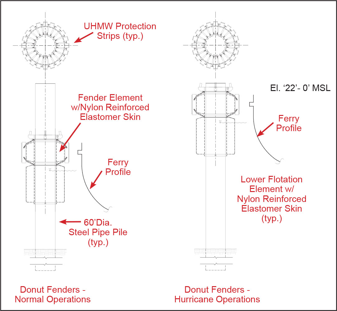
Figure 3. Donut fender and monopile detail.
The combo guide-on/berthing/mooring monopile system at each work dock will consist of four five-foot diameter steel pipe piles. The pile size was determined from the energy absorption requirement of the fender and the latter’s related minimum size, the soil lateral resistance, and the flexural and shear capacity of the monopile to resist the resultant fender reaction. The fenders will each be a nominal nine-foot diameter “donut” that will be placed over the steel piles (Figure 3). The selected fender has an energy absorption capacity of 198 feet-kips and associated maximum reaction force of 339 kips.
The “donut” consists of a closed cell polyethylene foam core that is protected by a tough, wear-resistant, reinforced polyurethane skin. The foam cell is attached around a steel core that is lined with low-friction bearings. The bearings allow the fender to rotate freely around the monopiles, and to rise and fall with changes in the water level. The piles were designed to be driven to depths of up to 100 feet below the mud line because of the presence of weak upper soil strata that are estimated to provide low to moderate lateral pile support.
Protecting the Uplands Infrastructure
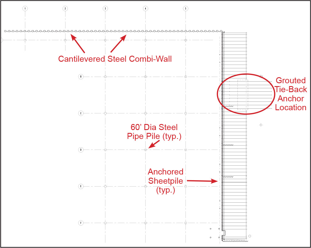
Figure 4. Overall piling plan.
There is evidence of overstressing and some cases of localized failure in the existing bulkhead along the eastern side of the property. To mitigate against further failure along the existing east bulkhead, and to protect the existing uplands infrastructure, a new three-part steel bulkhead was designed, as shown in Figure 4. The first and second parts are conventional anchored steel sheet pile bulkheads with different types of anchor systems. The tie-rod and concrete deadman anchor system were designed for 70% of the roughly 475 feet of east bulkhead. The remaining 30% of bulkhead will be restrained with a grouted tie-back anchor system.
The third bulkhead option was the design of a high strength, cantilevered steel combi-wall with high stiffness properties (large bending resistance). This type of bulkhead structure consists of a series of four-foot diameter steel pipe piles that are integrated with intermediate pairs of AZ-19 steel sheet piling. In this solution, the lateral earth pressures are transferred to the bulkhead through arching action of the soil. The use of this bulkhead type eliminates the use of any anchor system that would otherwise have to be installed on the Army Corp’s property.
Conclusion
These engineering solutions mean that TxDOT is well on its way to improving its maintenance capabilities and operations. The carefully planned construction phasing will allow TxDOT’s maintenance activities to continue with few disruptions. Construction started in April 2017 and is expected to take eighteen months.▪
Project Team:
Owner: Texas Department of Transportation, TxDOT, Houston District
Structural Engineer: Lockwood, Andrews & Newnam, Inc. (LAN), Houston, TX
Civil and MEP Engineers: LAN, Houston, TX
Geotechnical Engineer: Tolunay-Wong Engineers, Inc., Houston, TX
General Contractor: Texas Gulf Construction Company, Inc., Galveston, TX