
Situated near Boston’s original coastline and developed in the 17th and 18th centuries to increase waterfront real estate, Faneuil Hall Marketplace is one of Boston’s central meeting places. This popular location provides both residents and tourists a unique urban marketplace experience. The Marketplace is separated into four locations: Faneuil Hall, Quincy Market, North Market, and South Market.
Over the last decade, revitalization projects within the Marketplace continue, with the most recent being the replacement of a 1970s structure – a well-known large flower kiosk – with a new, one-story retail glass pavilion adjacent to Quincy Market.
48 Helical piles proved to be the most suitable and cost-effective piling option.
Project Challenges
The project team encountered a number of project challenges including construction in a sensitive, historic area, limited construction access in the dense urban environment, and difficult subsurface soil conditions that are commonly found in Boston’s reclaimed waterfront neighborhoods.
Structural column loads on the project site ranged from about 30 to 60 kips; however, the site provided many challenges.
Subsurface soil conditions at the site consisted of 9 to 14 feet of unsuitable urban fill (soil mixed with miscellaneous man-made debris) over up to 5 feet of soft organic silt, over thick natural marine deposits (clay, silt, sand), overlying glacial till. The upper portion of the marine layer was relatively stiff/dense and became softer with depth. Glacial till was approximately 60 to 70 feet deep. Remnants of previous structures, such as buried timber wharfs, were present in the fill to further complicate the already challenging subsurface conditions. Groundwater was encountered at 13 to 14 feet below the ground surface.
Geotechnical Design/Build Solution
Excavation, disposal, and replacement of the unsuitable fill and organic layers was deemed impractical due to premium costs associated with off-site soil disposal, excavation dewatering, and importing large quantities of structural fill.
The project team explored several piling options in lieu of excavation/replacement, including driven timber piles, drilled micropiles, drilled shafts, ductile iron piles, and helical piles. Driven timber piles were economically viable but were eliminated from consideration due to access issues and noise/vibration concerns. Drilled micropiles and drilled shafts both offered low-noise and low-vibration solutions but were too expensive. Ductile iron piles and helical piles were both appealing options due to ease-of-access, low vibration, and relatively low cost. The team ultimately selected helical piles as the most suitable and cost-effective piling option, as it offered low-noise and low-vibration where the Ductile Iron Piles could not offer low-noise.
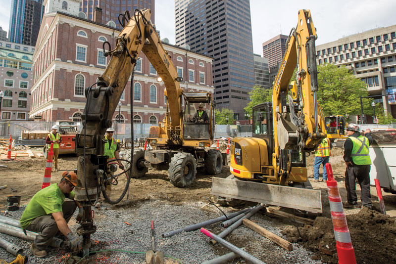
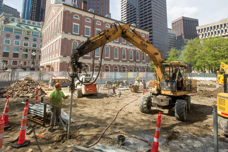
Helical piles support new glass building in Boston.
Helical piles are deep foundation elements that are used to support new foundations or underpin existing foundations. They generate no vibrations and can be installed with only 6 feet of overhead space and in other limited-access situations. The pile shafts are made of galvanized steel and are installed in short sections, each about 5 to 7 feet long. Each pile consists of a lead helical section with welded screw-like helix bearing plates; subsequent straight-shaft sections are mechanically fastened to the lead section as it is advanced into the ground.
The piles are installed with a skid-steer or an excavator equipped with a high-power torque head, which is calibrated to correlate torque resistance with axial pile capacity directly. Helical piles can also be installed with hand-held torque motors for locations that are not accessible with a skid-steer or small excavator.
Helical piles can function as end-bearing or side-friction elements. For an end-bearing pile, the lead section is advanced through the unsuitable soil layers and into an underlying bearing stratum until a predetermined design torque value is achieved. For a side-friction pile, “digger plates” are added between each pile section to create annular space around the steel shaft, and the annulus is filled with grout as the pile is advanced into the ground. This process creates a grouted bond with the surrounding soil, resulting in a helical micropile. Similar to a Drilled Micropile, a side friction helical micropile is installed to a predetermined design depth. At this point, the helices attached to the lead section aid in advancing the pile into the ground. However, due to a strain compatibility between a grout-to-ground bond and an end bearing plate, the torsional resistance should be ignored and only the bond length of the friction portion of the pile should be considered.
The Pavilion’s final structural design required 48 helical piles with an allowable compressive capacity of 30 kips each. The final pile design was performed by Helical Drilling and featured a galvanized 80 ksi steel pipe section manufactured by The Ideal Group. The piles consisted of a 2 7⁄8-inch-diameter, 0.276-inch-thick shaft with quadruple-helix (8-inch/10-inch/12-inch/14-inch) lead sections. The piles were designed to derive end-bearing capacity in the glacial till layer below the fill, organic silt, and marine layers.
Pile Installation
Before the installation of production piles, the General Contractor pre-excavated pile locations to remove potential obstructions, including timbers and granite blocks. Pre-excavation proved to be worthwhile, as all 48 piles were successfully installed at their planned locations. Upon completion, all helical piles were cut to their specified elevation, and the interior of the pipe shaft was filled with neat cement grout to provide additional corrosion protection and pile stiffness. All helical piles were installed in 8 days, which included mobilization and load testing.
Originally, the design of the helical piles was to achieve the required torsional resistance and capacity within the upper stiff layers of the marine clays. It is fairly common practice in the Boston marine clay deposits to attempt to achieve the capacity within the upper stiff layers. During some initial probing, it was found that the marine clays would not allow for the helical pile to achieve the required 30 kips of pile capacity. In actuality, installers were only able to achieve about half the required capacity. Therefore, it was determined that all helical piles should fully penetrate the marine clays and terminate within the glacial till deposit where achieving the torque and capacity was not an issue. This was deemed to be the most economical solution to avoid costly redesign of the foundation system to account for additional piles.
Quality Assurance and Control
Pile production included a full-time Quality Control person to oversee pile testing and installation. A full-scale compression load test was performed on a sacrificial test pile that was loaded to 200% of the design capacity. The test results showed deflection of less than ½-inch at design capacity and less than ½-inch of net deflection upon completion of the test. During load testing on the sacrificial pile, the interior was not grouted as with production piles. This was done to reuse the test pile at a production location. Therefore, the test pile did not get any benefits from the additional shaft stiffness through the softer marine clay and organic zones. As a result, no shaft buckling was observed during the test and may suggest that as long as there is soil, even at a weak density, it can provide sufficient confinement of the piles.
In this case, helical piles offered some key advantages, including low noise during installation, eliminated the need to export/import large quantities of fill, and did not require site dewatering.▪