
Lake Champlain is 125 miles long and separates New York and Vermont for much of its length. Discovered by Samuel de Champlain in 1609, the lake at its widest is 14 miles. Between Chimney Point, Vermont, and Crown Point, New York, it narrows down to about 2,000 feet. For many years, the only way to cross the lake was by ferry. Vermont was the early initiator for a bridge starting in 1923, and New York joined up in 1925. In 1926, borings were made at six possible crossing sites, funded by the federal government. In that same year, the Lake Champlain Bridge Joint Legislative Committee (New York State) requested the State Engineer and Surveyor to prepare a preliminary plan for a bridge at the site. On December 15th, the State Engineer recommended a tied arch on two cantilever arms making a total span of 320 feet, with 200-foot flanking spans. On May 11, 1927, the Lake Champlain Bridge Commission was formed with both states appropriating $200,000 for studies and designs.
Lake Champlain Bridge 1929-2012.
J. A. L. Waddell was called in to check three of the six possible bridge crossings and to make a recommendation to the Commission. He selected the Crown Point site and estimated a bridge could be built for $920,000.
For some reason, Waddell (then Waddell & Hardesty) was not selected for the design. On August 2, 1927, the Commission selected the Boston firm of Fay, Spofford, and Thorndike (FST) as their engineers. All three were MIT graduates and formed the firm in 1914. Spofford, then also a Professor at MIT, was the main designer. As was and still is common, the designer looks at various options as to the type of bridge. Since the channel could not be blocked during erection, the choice of bridge type would need to be built without falsework. In an article published in the Transactions ASCE, Spofford wrote:
The Commission and its engineers were in agreement that the bridge should have as pleasing an appearance as possible consistent with the foregoing. The historic importance of the site and the fact that the bridge would be conspicuous for many miles, on account of its height, made its appearance of special importance. Borings and test piles disclosed that the soil overlying the bed-rock[sic] was extremely soft and that the bridge piers would have to be carried to bed-rock[sic] which over a part of the site occurs at a depth of 100 feet below low water level. After consultation with Army officials, it was decided to provide a vertical clearance at the channel span of 90 feet above standard low water (Elevation 92.5) for a width of 186 feet, and a clearance of 73 feet above the same level for a width of 300 feet. The total width of the lake at this water level is approximately 1,500 feet. In selecting the type of bridge, consideration was given to the relative advantages and disadvantages of the following types: a) End-supported truss bridge; b) Cantilever truss bridge; c) Continuous truss bridge; and d) Suspension bridge.
Spofford rejected the simple span (end supported) truss stating, “The writer found it impossible to sketch any simple span design that was at all satisfactory in appearance.” He rejected the cantilever as it would have needed a short suspended span, which was also unsatisfactory with respect to appearance. This left the continuous truss span or suspension bridge. Spofford then tried two suspension bridge designs. One had a center span of 700 feet, with two flanking spans of 350 feet each and two 185-foot approach spans. The other had a center span of 1,000 feet with two flanking spans each with a length of 350 feet. He and the Commission agreed neither would look as well as the continuous span finally adopted. Spofford wrote of his decision to use a continuous truss:
The continuous truss type has all the advantages of the cantilever type except that of statical determination, and is also economical of material, especially when the dead stresses are large compared with the live stresses as in the case of a highway bridge with a concrete floor and with spans as long as those of this bridge. The lack of statical determination requires additional mathematical investigations on the part of the designers, but involves no special theoretical difficulties, merely increasing the labor of making the necessary computations. The deflection of a continuous span is less in amount and occurs with less rapidity than that of a cantilever span, this being an important element in favor of the continuous bridge. Moreover, the continuous type can be given a more pleasing appearance, consistent with economy, than any of the other types of truss bridges. One objection sometimes raised to continuous bridges is that settlement of foundations causes serious changes in truss stresses, but with piers supported on bed-rock[sic], as in the Lake Champlain Bridge, this objection does not exist.
The central part of the bridge had flanking spans and a main span that was to be continuous over two piers. Even though structurally different, the span resembled one proposed by the State Engineer and Surveyor, even to the curved lower chords of the flanking spans and a suspended deck for a portion of the central span. FST submitted its plans and estimate on November 15, 1927.
Structurally, and visually, it was similar to Smith’s Lachine Rapids Bridge (STRUCTURE, April 2017) in that the central span could be erected by cantilever methods using the flanking spans as anchor spans. Each cantilever would then be connected at mid-span to create the continuous span.
The 2,190-foot bridge, as designed and built, consisted of three plate girders of 50 feet each, and one simply supported 225-foot Warren deck truss, two continuous deck trusses (225 feet and 290 feet), the three-span deck to through truss (290 feet, 434 feet, 290 feet), one span deck truss (290 feet), with five plate girder spans on the Vermont side.
As to the computational methods used, Spofford wrote, “In designing the continuous trusses, preliminary stress computations were made using the values given in Griot’s tables of influence data for shear and moment for continuous beams of constant moment of inertia. In the main channel spans, the values of the dead reactions, as obtained at Piers 5 and 8 [ends of the central continuous spans] from the preliminary design, were used as final values. A clause was introduced into the specifications stipulating that these predetermined reactions should be secured by the use of hydraulic jacks fitted with gauges, and with the ratio between inches raised and reactions applied determined by actually raising the ends of the trusses before the laying of the concrete floor.
Before the final establishment of the reactions by jacking, the Method of Least Work was used to determine the dead-load reactions due to the steel work and the temporary tracks and concrete forms which were on the span prior to the jacking. The Method of Least Work was also used for a final determination of the live stresses, the irregular depth of the trusses in these spans making it seem advisable to obtain these stresses by a method more accurate than that used in the preliminary design.”
FST addressed the three main problems that engineers had with continuous truss design. Since the piers would rest on rock, the settlement would not be a problem. Using both the theorem of three moments with a constant E and I for preliminary design and later the Method of Least Work for final live load stresses, they refined the computational methods. Spofford based the size of the members in his continuous channel spans on the dead loads of the members plus the travelers.
Merritt-Chapman & Scott was awarded the contract to build the bridge on May 15, 1928, and work began on June 14. The American Bridge Company fabricated and erected all of the steel work. The total cost of the bridge was $967,800, and total cost of the project was $1,149,000. The bridge opened to traffic on August 26, 1929, on time and under budget. FST would later build similar bridges across Little Bay (275 feet) in Maine (The General Sullivan Bridge) and two across the Cape Cod Canal, the Sagamore (616 feet) and Bourne (616 feet) bridges.
With the completion of the Lake Champlain Bridge and the Ross Island Bridge (Portland, Oregon) by Gustav Lindenthal (one of the most vocal supporters of continuous truss bridges), more engineers accepted the merits of this type of structure, especially for highway purposes. Many engineers still believed, however, that long span simply-supported trusses were economically more efficient.
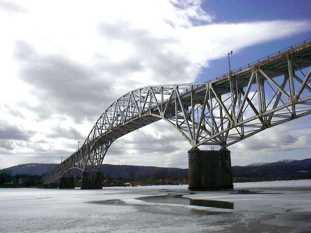
The Lake Champlain Bridge underwent repairs in 1991. In 2009, underwater investigations indicated the pier foundations were defective, and it was decided the bridge be replaced. As the DOT Regional Engineer said, “under certain conditions, we were afraid the bridge could fail abruptly.” A new design was prepared that was similar to that proposed by the New York State Engineer and Surveyor in 1927, in that the channel span consisted of two cantilever arms on which sat a tied arch. In 2011, the tied arch span, fabricated off-site, was floated into place and jacked up to sit on the cantilever arms. The old bridge was dynamited, dropped into the Lake, and removed. The new bridge opened on November 7, 2011.▪