
Brock Commons.
A Case Study in Tall Timber
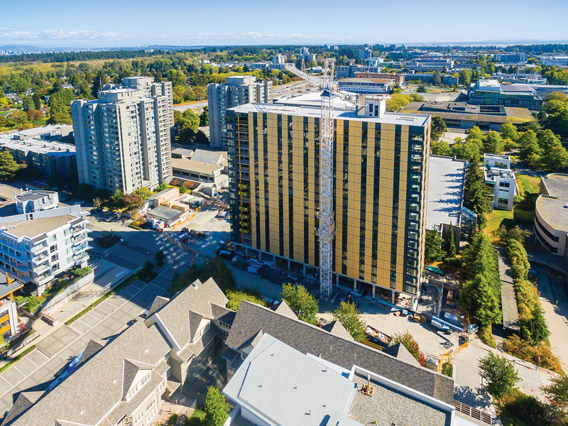
The tallest contemporary wood building in the world was recently constructed at the University of British Columbia (UBC) in Vancouver, Canada. Brock Commons is an 18-story student residence that is a mass timber hybrid and measures a record 174 feet (53 meters). Fast + Epp are the structural engineers, working in conjunction with Acton Ostry Architects and Hermann Kaufmann Architekten. (The Sakyamuni Pagoda of Fogong Temple built in China in 1056 stands 220.83 feet (67.31 meters) and is the tallest wood building in the world.)
Project Background
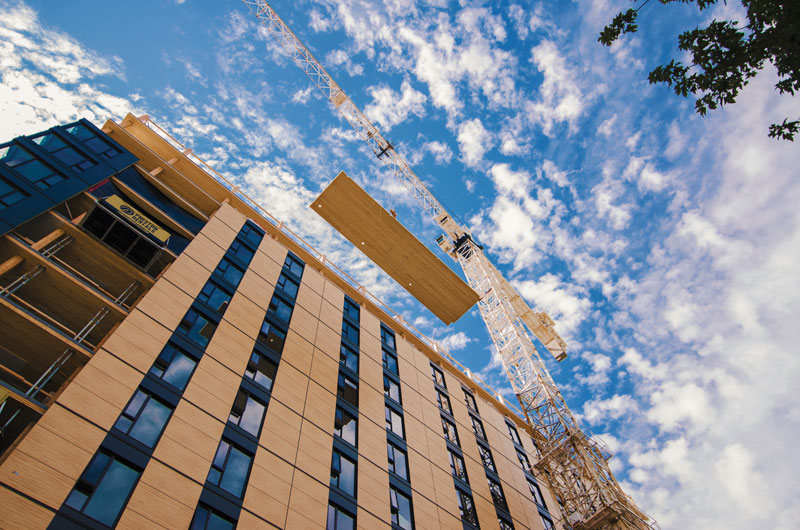
Figure 1. Timber erection – Summer 2016. Courtesy of Seagate Structures and Pollux Chung.
UBC is experiencing an increase in demand for student housing and has a sustainability commitment to a campus that acts as a “Living Laboratory” where innovation is encouraged, not only in academia but also in building and infrastructure. By pairing this drive with the potential for external funding related to mass timber research, the project was born.
The key goals of the project were to create a safe, functional, sustainable, and cost-effective residence for UBC students. Delivering a mass timber building with a construction cost that aligned with the unit cost of a comparable traditional concrete tower in Vancouver was an important goal, demonstrating the viability of wood as a practical material for tall building applications.
An integrated design team was assembled by the University to facilitate this effort. The construction manager was appointed, and the timber installer and concrete trades joined the team in a design-assist role, providing real-time feedback on the evolving structural design and offering valuable constructability advice.
The structure is comprised of 17 stories of five-ply cross-laminated timber (CLT) floor panels, a concrete transfer slab on the second floor, and a steel framed roof. The CLT panels are point supported on glulam columns on a 9.35- x 13.1-foot (2.85m x 4.0m) grid. Beams were eliminated from the design by utilizing CLT’s two-way spanning capabilities. Two full-height concrete cores provide the lateral stability for the structure.
Structural System
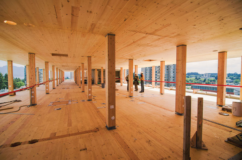
Figure 2. Point supported CLT system. Courtesy of Seagate Structures and Pollux Chung.
The design intent was to keep the structure simple and sensible: develop a prefabricated “kit-of-parts” that could be installed quickly and easily, with minimal labor on site.
CLT is often used as a one-way decking system, ignoring the two-way spanning capability afforded by its cross laminations. By utilizing CLT to span in both directions, the design team was able to eliminate beams, significantly reducing the overall structural depth (Figure 2). This created a clean, flat, point-supported surface, allowing for unobstructed service distribution as is commonly found in flat-plate concrete construction. Further, by adjusting the column grid and architectural program to suit the maximum available panel size, the team was able to both minimize the overall number of panels and maximize the efficiency of the system.
The primary lateral support for earthquake and wind loading is provided by two concrete cores. Although timber-based lateral force-resisting systems such as CLT walls/cores, timber braced frames, or post-tensioned/self-centering systems were feasible design options for this project, the testing, time, and costs required to obtain regulatory approvals would have negatively impacted the client’s budget and completion date.
Design Challenges
Codes and Standards
The current British Columbia Building Code (BCBC 2012) limits the height of wood buildings to six stories. As such, a special approval process was required for this project. The design is based on a Site Specific Regulation (SSR), administered by the Building Safety and Standards Branch of the BC Provincial Government, and is applicable solely to this project and site.
Due to the complexity of the project, two independent structural peer reviews were completed. The first independent review was timber-focused and was completed by Merz Kley Partner ZT GmbH in Dornbirn, Austria. The second was seismic-focused and was completed by Read Jones Christoffersen Consulting Engineers in Vancouver.
Prefabrication
Prefabrication is an essential consideration when designing large-scale wood structures. Well-planned erection and shop drawings are vital to ensuring smooth production and installation of timber elements. This results in fewer errors on the site, less remedial work, and a shorter overall construction schedule. All CLT and glulam elements were CNC machined with quality control protocols to better ensure a seamless erection of the timber superstructure.
To help achieve a high level of prefabrication for all design disciplines, CadMakers, a third-party consultant, modeled the building and helped coordinate design documents before and during construction. This 3D model, created with CATIA software, includes fully-detailed structural elements and connections, as well as mechanical/electrical systems, architectural fit-outs, formwork panels, and safety guards. The model allowed all CLT penetrations for mechanical and electrical sleeves to be fully coordinated during the design process and successfully converted into fabrication files (CAD/CAM) needed for CNC machining.
Point Supported CLT
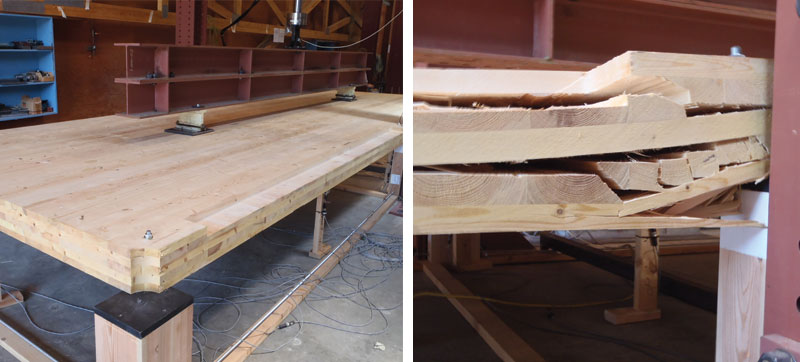
Figure 3. Point supported CLT panel testing apparatus (left); Failure (right).
In addition to stiffness and bending requirements, rolling shear stresses at the column supports are typically a controlling factor in two-way, point-supported CLT floor plates. A rolling shear failure is one in which the fibers “roll over” each other, due to shear forces perpendicular to the grain. After designing the custom lamination layup to suit the rolling shear and flexural demands, the design team completed 18 full-scale load tests, at the FPInnovations laboratory in Vancouver, on panels from three prospective CLT suppliers to validate the analysis. There appeared to be some capability for the CLT to redistribute forces, as internal shear cracks propagated through the panel before the critical failure mode occurred. Multiple types of shear/bending failures were observed near the supports (Figure 3).
Column Shortening and Shrinkage
In tall wood buildings, axial column shortening needs to be considered during design. When properly accounted for, the shortening should not negatively affect the construction, use, or long-term performance of the building.
Several factors affect glulam column shortening:
- Dead load elastic axial shortening (Δ = PL/AE)
- Live load elastic axial shortening (Δ = PL/AE)
- Shrinkage parallel to grain
- Joint settlement
- Column length tolerances
- Wood creep
The main concerns surrounding these shortening effects are the impact of the deformations on the vertical mechanical services, as well as the differential movement between the wood superstructure and the stiff concrete cores. The effects of these factors culminate at the roof level, where all columns below contribute to the shortening. A series of 1⁄16-inch thick steel shim plates were added during construction at the column-to-column connections on three strategic levels to mitigate a portion of these effects.
Monitoring
To better understand the unique behaviors of the building, the structure will be fitted with accelerometers, moisture meters, and vertical shortening string pots. Research teams at the University of British Columbia are undertaking this work as a part of the “Living Laboratory” initiative.
The data collected from the accelerometers and inclination gauges will help to verify the building’s performance in a significant seismic event. The string pots will measure the floor-to-floor axial column shortening at strategic levels, which will provide more insight into axial column shortening in highly loaded glulam columns. Lastly, moisture meters and data loggers will be installed in the CLT panels, collecting data from the manufacturing plant to the final installed condition. The meters will continue to measure moisture content throughout the service life of the building which, in a few years’ time, will give a moisture content timeline from fabrication to moisture equilibrium.
Construction
Proof of Concept Mock-Up
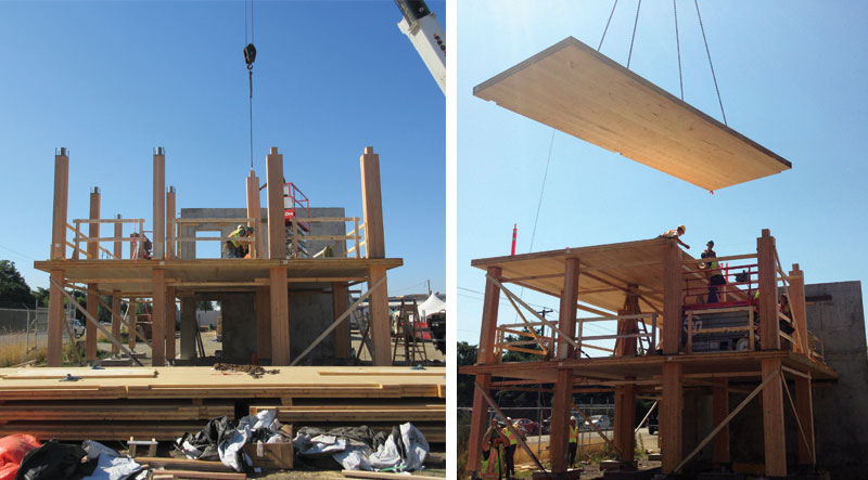
Figure 4. Proof of concept mock-up.
The construction team built a full-scale mock-up of a portion of the building to validate the constructability of the proposed design, 26 feet x 39 feet (8m x 12m) in plan and two stories tall. The mock-up included several connection types to help determine and optimize the details used in the final design (Figure 4). Also, the mock-up was used for the development and evaluation of various building envelope systems considered for the project.
Construction Sequencing
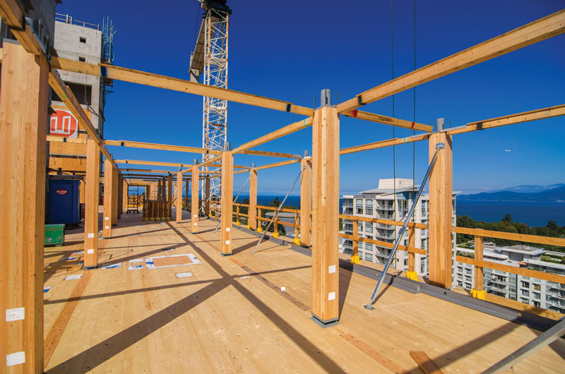
Figure 5. Braced columns. Courtesy of Seagate Structures and Pollux Chung.
The construction team erected the concrete cores to full height and installed the L2 transfer slab throughout the winter of 2015/16 to facilitate the use of one crane and provide sufficient time for manufacturing and shipping of the heavy timber elements.
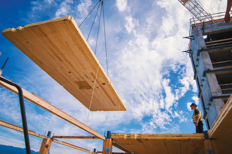
Figure 6. CLT panel installation. Courtesy of Seagate Structures and Pollux Chung.
In June 2016, the timber and envelope installation began. This was completed in four phases. The first involved erecting all columns on one level, diagonally bracing them, and using horizontal spreader bars at the column caps to set the grid (Figure 5). The columns were installed by hand from bundles on the active deck, freeing up the crane for envelope panel installation. The second phase was the installation of the CLT panels, stitching adjacent panels as the active deck moved away from the cores (Figure 6). The third phase was the installation of the steel drag plates at the concrete cores and perimeter angles to support the curtain wall system. The fourth was the installation of the envelope elements on the floor below the active deck (Figure 7). Erection of the timber and envelope panels was completed in just nine weeks, with the four-step installation sequence repeating itself.
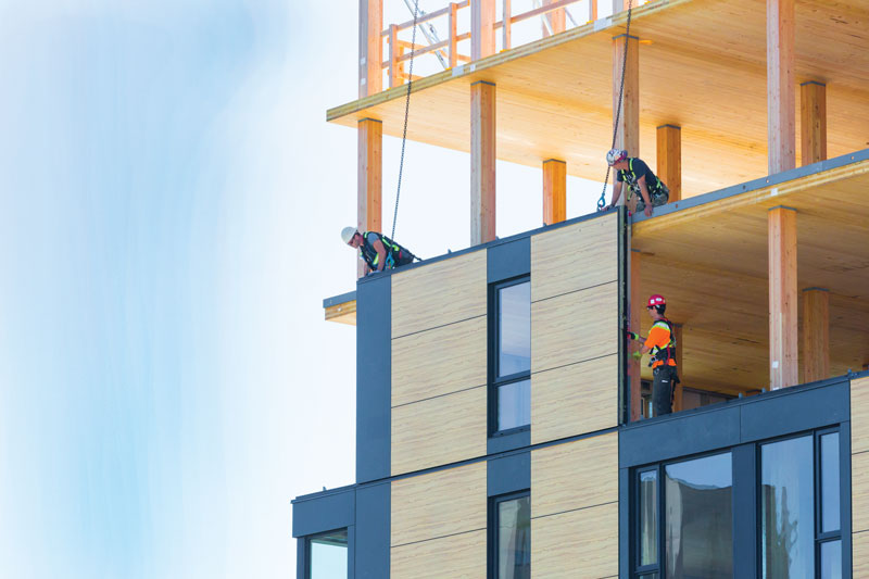
Figure 7. Perimeter envelope installation. Courtesy of Naturally: Wood and Steven Errico.
Conclusion
A mass timber building of this scale carries a unique set of engineering challenges, many of which can be mitigated through the use of innovative design strategies and strong quality control protocols. To date, the project has proven cost-competitive with concrete towers in the local marketplace, largely achieved by an integrated design team, real-time input from trades, and structural discipline. This large scale prefabricated project is a testament to fresh thinking and holistic design.▪
Paul Fast, P.E., P.Eng., Struct.Eng., FIStructE, is the Founding Partner of Fast + Epp. He is the structural engineer of record for the innovative 18-story Brock Commons student residence.
Robert Jackson, P.Eng., was heavily involved the design and construction of the Brock Commons student residence project.