
Per 2015 WFCM and 2015 SDPWS
In this article, a wood frame shear wall is analyzed and compared per American Wood Council’s 2015 Wood Frame Construction Manual (WFCM) and 2015 Special Design Provisions for Wind and Seismic (SDPWS). The difference between the segmented and perforated shear wall design approach and an overview of various hold-down design methods is discussed. Designers will likely find that the 2015 WFCM contains time-saving features for calculation of loads and design of shear walls and other building systems and components within the scope of the document.
2015 WFCM
The 2015 WFCM is referenced in both the 2015 International Residential Code (IRC) and the 2015 International Building Code (IBC). The WFCM includes prescriptive and engineered design provisions for wood wall, floor, and roof systems and their connections. A range of structural elements is covered, including sawn lumber, structural glued laminated timber, wood structural sheathing, I-joists, and trusses. While the WFCM is geared primarily to one- and two-family dwellings, IBC 2309 also allows the WFCM to be used for small commercial applications assigned to Risk Categories I and II. As an example, a single-story, slab-on-grade, light commercial structure with building length and width less than 80 feet (i.e., restaurants, office buildings, etc.) could be designed for lateral (wind or seismic) and gravity loads per the WFCM.
ASCE 7-10 Load Provisions
Tabulated engineered and prescriptive design provisions in WFCM Chapters 2 and 3, respectively, are based on the following loads from ASCE 7-10 Minimum Design Loads for Buildings and Other Structures:
- 0 to 70 psf ground snow loads
- 110 to 195 mph 700-year return period 3-second gust basic wind speeds
- Seismic Design Categories A – D
Additional information concerning changes to 2015 WFCM appeared in STRUCTURE magazine’s February 2015 issue.
2015 SDPWS
The 2015 SDPWS contains provisions for design of wood members, fasteners, and assemblies to resist wind and seismic forces and is referenced in the 2015 IBC Chapter 23 on wood for the design of lateral force resisting systems. It contains many updated provisions to provide consistency with ASCE 7-10 and is also referenced in ASCE 7-16. Additional information concerning changes to 2015 SDPWS appeared in STRUCTURE magazine’s July 2015 issue.
To facilitate the following design example, a free non-printable PDF version of the 2015 SDPWS and 2015 WFCM is available from the AWC website for those who do not already have a copy of the standards.
Wood Shear Wall Design Example
The following design assumptions are used for development of a comparison of shear wall designs using the 2015 WFCM and 2015 SDPWS. Gypsum is assumed as interior shear wall sheathing, but the approach will show the difference when not including its capacity. Both the segmented shear wall (SSW) approach and perforated shear wall (PSW) approach are utilized and compared. Note this is not a comprehensive shear wall design. Issues such as deflection, wind uplift, base shear, and summing hold-downs from upper floors are not addressed.
Summary of Design Assumptions
- 130 mph (700-yr, 3-second gust) Exposure B
- L=36 feet
- W=30 feet
- 5/12 roof pitch
- Top plate to ridge height = 6.25 feet
- 2-story
- 8-foot wall height
- 6.75-foot door height
- 4-foot window height
- Wood Structural Panel (WSP) Exterior Sheathing
- Vary interior walls – with and without ½-inch gypsum
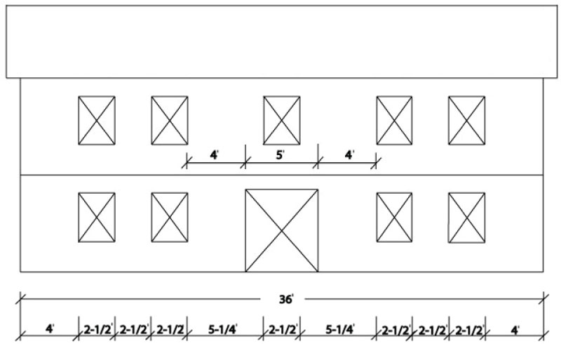
Figure 1. Elevation view of the structure used in a wind load design example comparing shear wall design procedures.
Figure 1 provides an elevation view showing window and door openings. Only first-floor shear walls and hold-downs will be analyzed in this example.
2015 WFCM Prescriptive – Segmented Shear Wall
The 2015 WFCM Table 3.17A gives length requirements for an SSW resisting wind loads. For a 30-foot building wall length, W, the interpolated value is 12.3 feet. Table 3.17A, Footnote 4, provides required sheathing length adjustments based on wall heights and top plate-to-ridge heights other than what is assumed in the table – which is 10 feet for each. For this example, the adjustment is 0.68. Therefore, an SSW would require 8.4 feet of full-height wall segments. Figure 1 shows 4 feet of shear wall at each corner and 2.5 feet between the windows for a total of 13 feet, which is sufficient. Hold-downs are required at the ends of each segment and will be designed later (Figure 2).

Figure 2. Comparison of shear wall requirements for a segmented vs. a perforated shear wall using 2015 WFCM prescriptive design provisions and assuming contribution of gypsum capacity.
WFCM Table 3.17D facilitates variation of exterior and interior sheathing materials, nail diameter and spacing, panel thickness, and stud spacing. WFCM shear wall baseline assumptions are 7⁄16 wood structural panels on studs at 16 inches on-center, 8d common nails, 6-inch panel edge nail spacing, and 12-inch panel field nail spacing (6 and 12). Shear wall tables for wind also assume contribution of half-inch unblocked interior gypsum. Note the allowable stress design (ASD) unit shear capacity of 436 plf for wind and a maximum shear-wall-segment aspect ratio of 3.5:1. All shear wall capacities in Table 3.17D are derived from the 2015 SDPWS.
Table 3.17D, Footnote 2, requires blocking of gypsum wallboard edges where the aspect ratio exceeds 1.5:1. SDPWS does not contain aspect ratio limits for the case where exterior and interior sheathing materials are combined for wind resistance. SDPWS does state that unit shears can be combined. Prior practice within WFCM for aspect ratios has been to limit use of the combined materials to the higher aspect ratio material. For example, WSP alone has a maximum aspect ratio of 3.5:1. Blocked gypsum wallboard has a maximum aspect ratio of 2:1. WFCM has permitted the use of combined resistance resulting from WSP exterior sheathing and blocked GWB interior sheathing on walls with an aspect ratio up to 3.5:1.
What if interior gypsum capacity is excluded from wind design? There may be cases, such as unfinished garages, where there is no interior gypsum. Note also, if contractors don’t install gypsum with assumed nail spacings, it doesn’t provide additional shear capacity for which it is designed. The capacity shown in Table 3.17D is 336 plf (gypsum is assumed to have 100 plf capacity for wind), and an adjustment factor of 1.3 is tabulated which can be used to adjust sheathing length requirements that were calculated from Table 3.17A earlier. That would then require 10.9 feet of sheathing length rather than 8.4 feet. In this particular example, if interior gypsum is excluded, the 13 feet of full-height segments determined earlier is sufficient. As noted, hold-downs are required at the ends of each segment (Figure 2).
2015 WFCM Prescriptive – Perforated Shear Wall
For the PSW approach, the entire wall is sheathed on one or both sides with wood structural panels. For wind design, interior gypsum can also be used additively with exterior wood structural panels. The contribution of sheathing above and below window openings, and above the door opening, can also be included. Nail spacing requirements for WSPs may be decreased (e.g. from 6 and 12 to 4 and 12). By increasing wall capacity, hold-downs can be eliminated around window and door openings. This is a major benefit of the PSW method.
WFCM Table 3.17E is used to determine the PSW full height sheathing adjustment. There is a 6.8-foot door opening in the middle of the wall, which will be used as the maximum, unrestrained opening height. The full-height sheathing length required for the SSW was 8.4 feet when including gypsum. The PSW length adjustment is based on the tabulated length of SSW required. So, 8.4 feet divided by the full wall length is 23% of full-height sheathing. Interpolation gives a factor of 1.86. Multiplying by the length required for the segmented method results in 15.6 feet.
Without interior gypsum, the segmented method required 10.9 feet which is 30% of full-height wall sheathing. So, the 1.72 factor from WFCM Table 3.17E results in 18.7 feet required for the PSW. Either one of these results is sufficient because there are 21 feet of full height wall sheathing. The 21 feet of full-height sheathing is based on wall portions that meet maximum aspect ratio limits.
As noted, a major benefit of the PSW method is that, for examples such as this, hold-downs are only required at the corners. By simply accounting for the benefit of a wall fully-sheathed with WSPs, which is fairly common in most parts of the country, hold-downs can typically be eliminated around window and door openings (Figure 2).
2015 WFCM Prescriptive – Hold-Down Capacities
In the WFCM, overturning loads are differentiated from uplift loads. Overturning moments result from lateral loads which are resisted by shear walls. Uplift forces arise solely from wind uplift on the roof and are transferred directly into walls supporting roof framing. A conservative assumption of WFCM tabulated hold-down capacities is that ASD unit shear capacities for the reference shear wall are multiplied by wall height to determine maximum hold-down capacity. Therefore, the same hold-down capacity can be calculated for both the SSW and PSW. Calculating the wind hold-down capacity in WFCM Table 3.17F is based on both wood structural panels and gypsum, resulting in 3,488 pounds for this example. If gypsum is excluded, then the capacity is lower. Table 3.17F, Footnote 1, states that the tabulated hold-down capacity is divided by the sheathing type adjustment factor from Table 3.17D, which is 1.3 as determined earlier, so a 2,683-pound hold-down is required if excluding gypsum. Note also that hold-down capacities are tabulated per story. Required hold-down capacities need to be summed from the story above, but are not shown in this example for simplicity.
Another conservative assumption in WFCM Prescriptive Design provisions (Chapter 3) is that design dead load is only used to offset uplift loads and not overturning loads. However, WFCM Engineered Design provisions (Chapter 2) allow for up to 60% of design dead load to offset overturning. Of course, engineering judgment is required to determine what portion of design dead load is tributary to the hold-down, which is a major reason for the conservative approach.
2015 WFCM Engineered – Segmented Shear Wall
Engineered requirements in WFCM Chapter 2 allow calculation of loads that are assumed in the prescriptive requirements of WFCM Chapter 3. WFCM Table 2.5B shows lateral loads on the roof and floor diaphragm. With a 5/12 roof pitch, a roof span of 30 feet and loads parallel to the ridge, interpolate 94 plf. Floor diaphragm load is 105 plf (after a wall height adjustment per Footnote 2). Add those up for 199 plf, multiply by building width, and divide by two because half the load goes to each shear wall. The result is 2,985 pounds at the top of the first-floor shear wall.
The 2015 WFCM references 2015 SDPWS for shear wall capacities. However, as discussed earlier, WFCM Table 3.17D tabulates 436 plf and 336 plf shear wall capacities for this example, with and without gypsum, respectively. Therefore, length requirements are:
- 2,985/436 = 6.8 feet (with blocked gypsum)
- 2,985/336 = 8.9 feet (without gypsum)
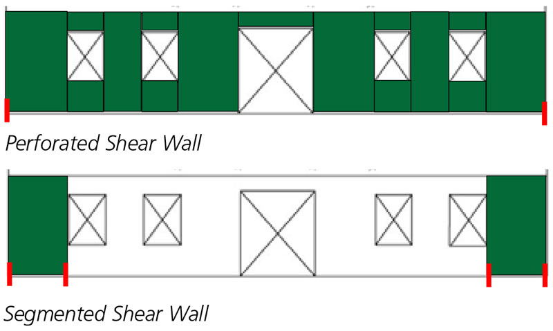
Figure 3. Comparison of shear wall requirements for a segmented vs. a perforated shear wall using 2015 WFCM engineered design provisions and assuming contribution of gypsum capacity.
Based on these results, the 4-foot segments at each building corner are sufficient if blocked gypsum is included in the shear wall capacity (Figure 3). This also shows that the WFCM engineering provisions provide more efficiency in the design process than the prescriptive design provisions.
2015 WFCM Engineered – Perforated Shear Wall
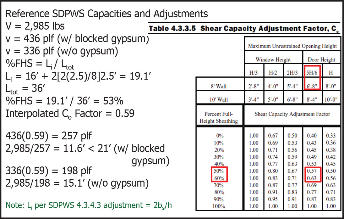
Figure 4. Summary of perforated shear wall calculations per 2015 SDPWS Table 4.3.3.5.
Figure 4 summarizes PSW calculations per SDPWS Table 4.3.3.5. Figure 3 shows the comparison of shear wall requirements for SSW versus PSW assuming gypsum contribution.
2015 WFCM Engineered – Hold-Down Capacities
WFCM section 2.2.4 allows for offsetting hold-down capacity with up to 60% of design dead load. The same approach for determining hold-down capacities based on ASD unit shear wall capacity is used for this example. Therefore, hold-down capacities are as shown earlier for the prescriptive design approach.
2015 SDPWS – Segmented Shear Wall
SSW design per the SDPWS is identical to what was shown earlier under the WFCM Engineered approach. As noted, the WFCM references the SDPWS for shear wall capacities.
2015 SDPWS – Perforated Shear Wall
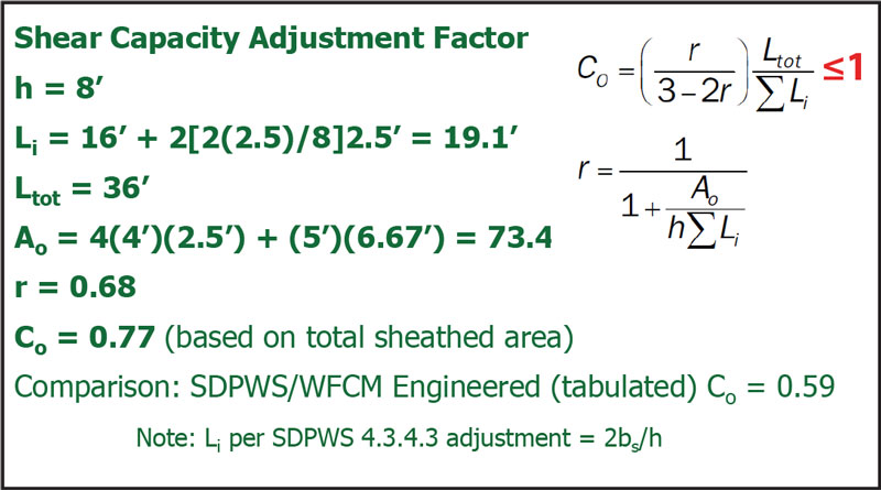
Figure 5. Calculation summary of PSW shear capacity adjustment factor per 2015 SDPWS Equations 4.3-5 and 4.3-6.
Figure 5 summarizes PSW calculations per SDPWS Equations 4.3-5 and 4.3-6. These equations provide more accuracy by allowing the total sheathed area to be included in capacity calculations. Note that SDPWS Table 4.3.3.5 and WFCM Table 3.17E both use maximum opening height and, for example, do not account for sheathing below window openings. Adjusting the shear wall capacity of 436 plf (with blocked gypsum) and 336 plf (without gypsum) by Co = 0.77 results in shear wall lengths of 8.9 feet and 11.6 feet, respectively.
2015 SDPWS – Hold-Down Capacities
There is a difference in how hold-down capacities are calculated in SDPWS versus WFCM. Per SDPWS Equation 4.3-7 for SSW, hold-down capacity is based on induced unit shear. The 2,985-pound load and 8-foot shear wall length result in 347 plf. The shear wall height of 8 feet results in a hold-down capacity of 2,985 pounds. Excluding gypsum, a hold-down of 1,840 pounds is calculated.
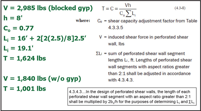
Figure 6. Summary of perforated shear wall calculations of hold-down capacity per 2015 SDPWS.
For the PSW, SDPWS Equation 4.3-8 can be used, which accounts for the shear capacity adjustment factor determined earlier and the 2bs/h adjustment per SDPWS 4.3.4.3. Figure 6 summarizes PSW hold-down calculations.
Summary and Conclusion
| AWC Standard | Segmented | Perforated | Hold-Downs, lbs |
| 2015 WFCM Prescriptive | 8.4′ (10.9′) | 15.6′ (18.7′) | 3,488 (2,683) |
| 2015 WFCM Engineered | 6.8′ (8.9′) | 11.6′ (15.1′) | 3,488 (2,688) |
| 2015 SDPWS | 6.8′ (8.9′) | 8.9′ (11.6′) | 2,985 (1,840) [SSW]
1,624 (1,001) [PSW] |
(Parenthetical values assume NO interior gypsum capacity)
Table 1 provides a summary comparison of various methods used for this wood shear wall design example. WFCM prescriptive design provisions have an engineering basis in SDPWS and ASCE 7, even though simplifying assumptions are made which lead to more conservative results. WFCM engineered and SDPWS results are nearly identical, which is expected, except for the PSW design. The difference in the PSW results is due to SDPWS equations being used to calculate the shear capacity adjustment factor, rather than using tabulated values. The segmented approach results in less shear wall length in all cases; however, hold-downs are only required in the corners for the PSW. By simply accounting for the benefit of a wall fully-sheathed with WSPs, which is fairly common in most construction today, hold-downs can typically be eliminated around window and door openings. Not surprisingly, where the most efficiency is gained is with the pure SDPWS engineering approach. Shorter shear walls and smaller hold-downs result. However, designers might find the WFCM tables to be a time-saving feature, especially for calculating ASCE 7 wind loads.▪
This article is based on an NCSEA Diamond Reviewed program titled DES413-2 – Wind Shear Wall Design Examples per 2015 WFCM and 2015 SDPWS available for free on the AWC website. Earn continuing education credits or find more details about this shear wall example at www.awc.org.