
The Sciotoville Bridge, designed by Gustav Lindenthal (STRUCTURE, August 2010) over the Ohio River, is located about 90 miles upstream from Cincinnati. The Chesapeake and Ohio Railroad, in order to make Chicago accessible for its coal-carrying trains out of Kentucky, built a 30-mile line from its tracks in Edgington, Kentucky northerly across the Ohio River to Waverly where it connected with a line to Columbus, Ohio and then on to Chicago. The Ohio was about 1,500 feet across at the selected site, with bedrock only 10 feet or so below low water. The Ohio had been bridged for railroads several times by Jacob Hays Linville and others, starting with the Steubenville, Parkersburg, and Benville Bridges upstream and downstream at Cincinnati. The railroad was looking for a twin track structure that would meet demands of the War Department to provide for passage of steamboats.
Lindenthal, as was his custom, looked at all types of bridges that had been used to carry heavy railroad loadings over long spans. He determined that a continuous truss with two spans of 775 feet best met the site conditions. The fact that rock was accessible at a shallow depth removed one of the factors that ruled against continuous spans in the past – settlements of the central piers could be eliminated. The other reason continuous spans were not adopted, with notable exceptions of C. Shaler Smith’s Lachine Rapids Bridge (STRUCTURE, April 2017) across the St. Lawrence and Lindenthal’s two smaller, shorter span continuous spans in the Pittsburgh area in 1883 and 1890, was the difficulty in making calculations for an indeterminate structure. He indicated that temperature effects were minimized in his design with a fixed support at the river pier and rollers at the abutments. With the help of O. H. Ammann and D. B. Steinman, Lindenthal designed the longest continuous span in the United States. The main advantages of the continuous structure were savings in material and its ability to be constructed by cantilever methods. He estimated savings in the material of nearly 25%, with an increased rigidity when compared to a cantilever bridge and an equal rigidity when compared to the simple span truss. He also stated, “From the esthetic point of view, the continuous bridge can well compete with the simple span or cantilever, if properly designed, but not with the more artistic arch or suspension bridge.”
Lindenthal incorporated a unique inverted two-hinged arch, building the floor beams into the verticals, with the thrust at the upper ends being taken by the upper lateral bracing This design allowed for smaller floor beams to span the distance between trusses, which were 38 feet 9 inches center-to-center.
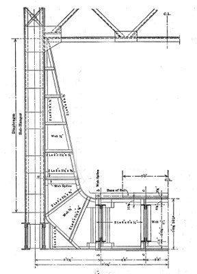
Rigid frame tying floor beams into truss verticals.
First, he designed trusses with 16-inch eye bars for all tension members that would not see a reversal of stress under live load. He then designed all members built up of riveted members and fully riveted connections and requested bids on both designs. The cost of steel came in lower with the eye bars, but he chose the fully riveted structure “in view of its superior rigidity, durability, and safety.” Moreover, finally, Lindenthal calculated the secondary stresses that would occur under normal erection procedures and found them very high. He wrote, “on account of the rigid truss connections; it was considered advisable to reduce the secondary stresses as far as possible, not only near the center support but throughout the truss, in the chords as well as in the web members.” This was done by cambering the trusses for full dead load plus one-half the live load, covering both spans, but assembling and erecting them so that the angles between the members and the bevels of the joints would correspond to the geometric form of truss. In other words, under the load (d+ ½ l), the trusses are calculated “to assume their true geometric form and the members to become straight and free of secondary stresses.” He determined his “secondary stresses under dead load only are equal, but of opposite sign, to those under full live loads covering both spans, and, in absolute value, equal to one-half of those which would be produced by full live load if the angles between the members would correspond to the cambered form of truss.” This cambering of the trusses required that members be preloaded to allow connections to be made that resulted in the cambering he needed. This was the first time that this expedient was utilized in American bridge building. Building on temporary falsework by cantilever methods also resulted in many different loading conditions of his members during erection and after completion. As would be expected, he used all of these various loading conditions to determine the maximum load that would fall on each member and designed the member to resist that load.
For his erection process, he built the Ohio side of the bridge on false work but could not use as much falsework on the Kentucky side. He, in association with McClintic Marshall, the contractor, built the Ohio side on falsework and then cantilevered out to the eighth panel point from the Kentucky side and placed a steel bent in the river. He then jacked up the span a desired (calculated) amount and continued cantilevering out to the fourth panel point from Kentucky and jacked up the span once again. He completed the span by cantilevering out to the Kentucky abutment. When the span reached panel point, Lo, the truss was 16¼ inches low at which time the end was jacked up and set on the rocker bearings. The superstructure was finished on August 17, 1917.
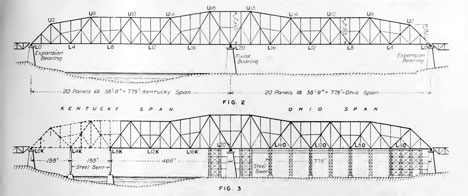
Sciotoville truss work and falsework supports.
The Engineering Record published an article on the bridge and in an editorial wrote:
“In the final selection of type of structure, the particular nature of the profile at the crossing, the clear opening required during erection and the nature of the foundations at possible locations of piers or abutments are all determining factors. The advantages in erection and the fact that solid rock foundations were found at small depths so that the settlement at the piers should be practically negligible, were the most important considerations in the selection of the continuous [structure] type in this case. Economy for this type can generally be easily shown…The indeterminate character of the stress analysis is also generally considered a disadvantage. The experience with the Queensborough Bridge may be cited in this connection. The continuous span on many supports was shown by the report of the investigation engineers to be designed with astonishing errors in the distribution of the metal…It is notable, however, that methods of treating indeterminate structures are now becoming well standardized and should soon be simplified into such form as to make the cost of designing low.”
Lindenthal did not describe the bridge in the Transactions of ASCE until 1922 when he wrote a 43-page article entitled, “The Continuous Truss Bridge over the Ohio River, at Sciotoville, Ohio of the Chesapeake and Ohio Northern Railroad.” Engineering and Contracting ran a long article based on the ASCE piece in its April 22, 1922, issue. After giving a brief history of continuous bridges in Europe and the United States, Lindenthal challenged the reluctance of his fellow engineers to utilize the continuous truss writing,
“The continuous truss type has nowhere met with more indiscriminate and unqualified condemnation than by engineers in the United States who have alleged three principal objections against it, none of which is novel or decisive:
1st – That it is statically indeterminate, that is, its reactions and stresses are dependent on the elasticity of its members;
2nd – That it is subject to stresses from unequal settlements of its supports; and,
3rd – That it is affected by temperature changes.”
He then made his case as to why none of these objections apply to his Sciotoville Bridge and proceeded to describe his structure as follows.
General Proportions – The steel superstructure, as built, is a double-track, two-span, continuous bridge, with a total length of 1,550 feet between centers of end piers, or two equal spans of 775 feet and two clear openings of 750 feet at low-water level.
To obtain ample lateral rigidity, the width between centers of trusses was [a] somewhat smaller width than was considered sufficient, in view of the continuity of the lateral truss. The height at the middle of each span is 103 feet 4 inches between centers of chords. To fix this height, the portion of the span between the end pier and the point of contra flexure was considered as a simple span. This portion varies from three-fourths of the span length for uniform load on both spans to seven-eighths of the span length for uniform load on one span only and averages 630 feet in length. The height of the truss was chosen approximately one-sixth of this length.
The height over the center pier is 129 feet 2 inches or one-sixth of the span length; this is the proper height for a simple span of the same length, which has the same maximum moment at the center as the two-span continuous bridge over the middle support.
The height at the end was made 77 feet 6 inches, or equal to a double panel, in order to give the end posts an inclination of not less than 45 degrees. These heights also secured a pleasing outline for the top chord. The web system is of the Warren type, with subdivided panels of a uniform length of 38 feet 9 inches, which was found to be the most economical.
The discussion of the article ran 21-pages. C. A. P. Turner wrote a seven-page response whose main point was that two simple spans would have been cheaper and concluded that Lindenthal’s “preference for the continuous bridge of moderate span differs from the majority opinion of American bridge engineers, because of lack of demonstrated economy on a scientific, mathematical or design basis.” J. E. Greiner wrote praising Lindenthal, “It may be said also that, in every structure of importance designed by Mr. Lindenthal, there is evidence of this genius which originates. Each of his structures is practically a new creation as compared with the ordinary and stereotyped bridges throughout the United States. The Sciotoville Bridge is no exception. It is a daring and handsome structure, decidedly, ‘Lindenthalic’ in all its features…” Charles Fowler wrote, “The Sciotoville Bridge is a striking example as to what may be accomplished in the use of the continuous bridge. It is the longest of that type ever constructed and now gives America the proud distinction of having the longest spans for every type of bridge construction.”
Lindenthal responded to the individual commenters, taking exception to Turner’s claim that two simple spans would have been less expensive. As to J. E. Greiner’s discussion in which he argued that Lindenthal had not designed the bridge to Cooper’s E60 loading, Lindenthal wrote that Greiner, “was unjustified and made without examination of the requirements of the writer’s specifications other than the basic unit stress (20,000), which may mislead superficial readers.” He commended Steinman’s contribution but disagreed with Steinman’s remark that reducing the height of the trusses over the middle pier and increasing the height at mid-span “would not be on the whole, advantageous or economical.” Steinman had written, “The Sciotoville Bridge is a striking example of scientific design. It represents an unusually intensive application of engineering theory and resourcefulness to the determination of the most efficient disposition of the materials of a structure, and to the rigorous advance planning of every step in the operations of fabrication and erection.” Steinman had also written an article for the Engineering Record on August 28, 1915, entitled “The Elastic Curve Applied to the Design of the Sciotoville Bridge.”
It is evident from the record that most bridge builders in the United States were still not ready to adopt continuous bridges and preferred long simple truss spans or cantilevers. Shortly after the bridge was opened, the Bessemer and Lake Erie Railroad built a continuous bridge over the Allegheny River near Pittsburgh with spans of 272 to 520 feet. The Hudson Bay Railway built a bridge over the Nelson River in 1918 with spans of 300 to 400 feet.
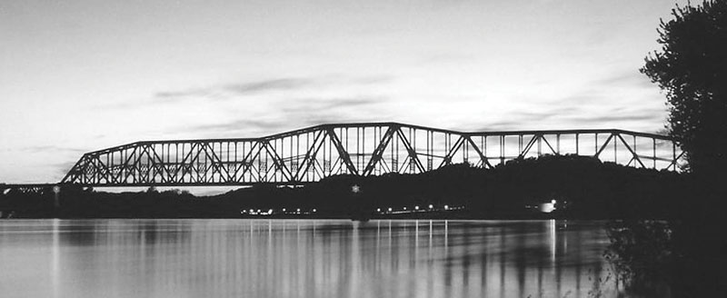
Sciotoville Bridge (color postcard author’s collection).
When opened, the Sciotoville Bridge’s 775-foot riveted spans were the longest continuous truss spans in the world until the opening of the Duisburg-Rheinhausen Bridge in Germany in 1945 with its 835-foot spans. With its rigid construction, Lindenthal’s continuous truss bridge serves the Chesapeake and Ohio Railroad to this day.▪