
Many buildings are partially or wholly clad with stone. There are many aspects of stone anchorage that can, and do, affect the long-term performance of the building envelope and the initial and long-term costs of the envelope and building operation. This article presents critical stone anchorage issues with a focus on anchor and fastener selection and design based on the author’s experience.
Two of the most important things to consider when selecting and designing stone anchorage are:
- The size of the stone being installed: face dimensions, thickness, and shape.
- The backup system; this impacts anchor capacity and placement and will influence the amount of movement in the stone.
This article focuses on large-scale stone and is generally applicable to both natural quarried/cut stone and cast stone, although minor differences may exist between the two based on performance property differences. The code content included has been drawn from the 2015 International Building Code (IBC), the 2013 Building Code Requirements for Masonry Structures – TMS 402-13/ACI 530-13/ASCE 5-13 (TMS 402), and the 2013 Specification for Masonry Structures – TMS 602-13/ACI 530.1-13/ASCE 6-13 (TMS 602).
Stone Size Considerations
The IBC addresses stone veneer and slab type veneer in separate sections within Chapter 14 for Wall Coverings. Those sections, however, rarely are directly applicable to the large stone cladding that is considered in this article. For the purposes of this discussion, the assumption is that the stone veneer is to be anchored and that the stones require specific engineered anchorage.

Figure 1. Large scale stone – institutional project. Courtesy of Indiana Limestone Institute.
Large-scale stones are often used for monumental or significant projects where scale and aesthetics require the use of larger, often significantly larger, stones rather than those that can be secured with veneer type mortar bedded anchors. These large stones are usually anchored with four or more stainless steel anchor straps per stone fastened to the backup system. Anchors for large-scale stones can receive load from more than 20 square feet of cladding and must transmit several hundred pounds of force to the backup system. The anchors, also, must typically be placed at very specific locations, such as at the ¼ points of the units, to allow for loading by the stone above and below the anchor while maintaining consistent stone support and behavior. These potentially high anchor loads and specific location requirements typically preclude the use, or at least the easy use, of direct connection to stud framing. Therefore, a masonry or another solid backup system is preferred. Figure 1 shows a completed large-scale stone project and Figure 2 shows a large-scale stone project under construction showing strap anchors in place.
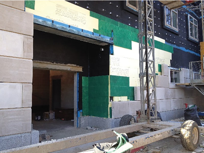
Figure 2. Large scale stone – institutional project. Courtesy of International Masonry Institute.
Anchorage Basics
Simple span type stone anchorage can generally be designed by hand analysis methods, although software applications can more accurately and efficiently accomplish the work. The effect of anchor location on anchor loading is based on tributary area, and that makes analysis easier for the anchor designer. Stones with reasonable size, geometry, and bonding allow the use of four anchor points per stone. The lateral load is distributed to the anchors based on tributary area. In rare cases where differential stiffness exists in the anchors or backup for a particular stone, it is desirable to employ finite element analysis (FEA). The same is true for longer stones with slender profiles, thin section stones, or stones too large to be anchored with only four anchors.
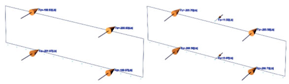
Figure 3. a) 2- x 8-foot limestone reactions (lbs.) with 4 anchors; b) 2- x 8-foot limestone reactions (lbs.) with 6 anchors.
When using FEA, both the stone and the anchor stiffness must be estimated as accurately as possible. This requires knowledge of the stone. Properties can vary by stone type and also within varieties of a particular stone type. Natural stone suppliers and cast stone manufacturers can provide the appropriate material information. Then, using FEA, the anchor reactions and internal stresses can be compared to the anchor and stone limits. Figures 3a and 3b contain reactions for a rectangular, large-scale stone where an additional anchor is added at the mid-point. It is often observed that simply adding an extra anchor may not relieve a minor over-stress and could, in fact, increase localized stresses or create a stress reversal in the anchors. This example demonstrates that adding an anchor may have little effect and could have even had a significant detrimental effect.
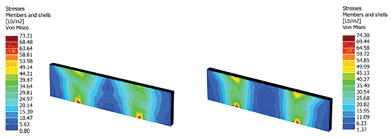
Figure 4. a) 2- x 8-foot Limestone Stresses (Von Mises, psi) with 4 anchors; b) 2- x 8-foot limestone stresses (Von Mises, psi) with 6 anchors.
When checking stone stresses, the use of Von Mises stress is a convenient check for natural (unreinforced) stone whereas large-scale cast stone will be reinforced and needs to be evaluated using reinforced concrete analysis. Figures 4a and 4b show the same stone pieces from Figures 3a and 3b but with the internal stresses highlighted based on anchor placement. Note that while there is little change, the addition of the extra anchors slightly increased the internal stress within the stone. Anchor reactions and stone stresses can be significantly affected by anchor location, stone thickness, and stone geometry – so the designer should be careful!
When evaluating stone stresses, keep in mind that many types of natural stone can have tested modulus of rupture values more than 1,000 psi. Safety factors must then be applied. The Indiana Limestone Institute (ILI) recommends not less than an 8:1 factor. For the 4-inch thick stone illustrated in Figures 4a and 4b, the minimum tested ultimate modulus of rupture value for limestone would need to be 586 psi and 594 psi, respectively – not a problem for most natural stones. If the values were higher, more anchors or thicker stone could be required.
Anchor Type Selection and Design
Most stone anchors are created from stainless steel flat stock. Analysis of the straps can be conducted using methods outlined in the Design Manual for Structural Stainless Steel (2006 Euro Inox and The Steel Construction Institute) or the Specification for Structural Steel Buildings (2010 AISC). Both provide methods and address strength/stress limits, buckling, etc., but neither document contains specific content for the design of simple flat strap elements. The author prefers, and typically uses, the AISC approach for better recognition of simple rectangular elements and its relative modernity.
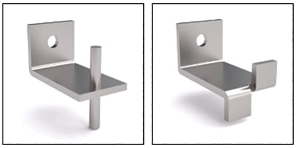
Figure 5. a) Manufactured strap anchor with dowel; b) Manufactured strap anchor with split-tail turns. Courtesy of Wire-Bond.
Most common anchor straps are 1/8-, 3/16– or possibly ¼-inch thick with widths that vary from 1¼ inches to 3 inches or more. The straps can have a single turn at the end or a ‘split-tail’ where one tab points up and the other down to engage stones on each side of the joint – typically bed joints but sometimes head joints in which the anchor is being placed. Other approaches include straps with dowel pins that engage holes in the stone, or straps with holes to allow the insertion of anchors into the stone edges. It is not recommended to use fasteners that impart expansive forces to the stone when anchoring into or near an edge. Figures 5a and 5b show examples of how these anchors tabs and dowels engage the stone by being placed into cut slots or holes in the stone. Fixity at the stone is determined by the material used to fill around the dowel or tab, as well as the joint filler material which ‘pinches’ the end of the anchor strap. If flexible materials are used, then a simple ‘pinned’ connection can well represent the joint. Fixity can be obtained using firm fill and mortar materials. Based on the stone end fixity, and with a reasonable degree of fixity at the backup end, a proper k-factor can be determined and tension/compression analysis conducted.
Flexure and shear in the tabs at the stone embedment and at the fastener end must be considered in addition to the axial force analysis. Prying considerations should also be included to address resulting strap and fastener load increases. Most straps can be designed thick enough to eliminate the prying concern. Punching shear should be evaluated in the stone, in accordance with the appropriate standards, although it will rarely control anchor design for 3- or 4-inch thick stone.
Example – Anchor Design
Consider a split-tail anchor strap similar to that shown in Figure 5b. The strap includes an offset dimension from the center of the fastener hole to the center of the outstanding strap of 1 inch, and it features ¾-inch high tabs, one turned up and one turned down. Typically, half of the anchor load will originate in each of the tabs although stone coursing of different heights can create some imbalance in the tabs. Usually, the flexure between the outstanding strap and the fastener will control the design due to the greater distance between lines of action. Using the anchor reactions from the diagrams shown in Figure 3a, let’s look at a strap design for 200 pounds in tension and compression. Remember that the anchor is also receiving a load from the stone above (in this case, an equal size stone), so the load applied is 2 x 200 pounds, or 400 pounds. The use of ASCE 7-10 will result in a wind load factor of 0.6 for allowable stress design, so the final ASD design load for the straps and fasteners would be 240 pounds. Expect one fastener to be required and try a 3-inch wide x 3/16-inch thick strap to moderate the steel stresses and prying action. Assuming rigid fill and checking axial plus flexure at the backup surface bend, base the calculations for axial compression on a ‘k’ factor of 0.8 to allow for some movement. Using AISC Section E3, the axial compression capacity with an 8-inch dimension from the face of backup to the back of the stone is 5,051 pounds. The axial tension capacity is 8,421 pounds. With the ¾-inch offset creating a ¾-inch moment arm, the flexure in the elbow is 180 in.-lbs which would be compared to a capacity of 395 in.-lbs.
As you can see, in this, as in many cases, flexure is the dominant aspect in the anchor design. Combined stresses indicate a utilization of approximately 50 percent under these conditions. Deflections can be checked but will usually not control, especially when the stresses are this low. Checking manufacturers’ product information shows several options that can work. As mentioned before, prying should also be checked, at least until a feel is obtained for the limits where it will not control. In this case, the combination of the fastener diameter and plate width/thickness indicate that prying does not need to be considered when using AISC Part 9 for the evaluation of connecting elements.
Other Considerations
Overhead Stone Anchorage is an art form within the larger stone anchorage discipline. Gravity load support generally demands higher safety factors and specific overhead anchor types. Mechanical and plate type anchors are most common and often include an adjustment in one or more planes to allow field fitting and tuning of stone placement. Epoxy anchors can aid in the installation of overhead anchors, but restrictions and concerns about long-term capacity and fire/heat degradation of the adhesive should be carefully evaluated before implementation.
Opening Surrounds and Other Special Applications create unique anchor load and stone stress conditions. Out-of-plane, gravity, and rotational stability of the stone pieces must be considered with solutions including anchors and mortaring. The sequential fit-up of the stones in unique assemblies can be challenging in the field, and the anchor placement should be coordinated with the contractor’s installation sequence.
Backup Types for Stone Anchorage
Stone cladding may be applied to any backup system, but the most common applications for large-scale stone include concrete masonry and or concrete. The primary points of interest related to stone backup should be anchor capacity and location, as well as backup load capacity and deflection under load. Another consideration would be system longevity. Nobody wants to invest in a ‘forever’ cladding of stone for their building only to have it fail due to the poor structural performance of the backup, or to have to remove it to repair or replace a backup system that hasn’t withstood the test of time.
Fastening methods for connecting stone anchors to the backup vary based on the type of backup system being used. Direct tension screw fasteners work well and are most common in solid substrates such as concrete masonry and concrete. Fastener capacity values are high even for modest size fasteners. Locational concerns are generally not present due to the solid and continuous substrate presented by masonry and concrete. This is because anchors may be located as needed by the stone layout for optimized efficiency to provide secure and permanent anchorage of the stone veneer. When working with solid substrates, multiple anchors can easily be placed side-by-side or at stone-specific locations while retaining their effectiveness, subject to possible fastener capacity reductions based on the fastener spacing.
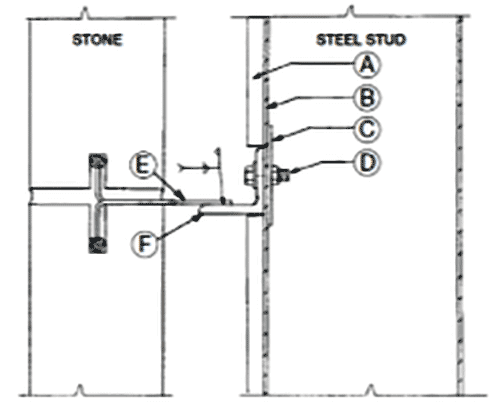
Figure 6. Split-tail strap anchor with a horizontal distribution angle for anchoring to a metal stud backup system. Courtesy of Indiana Limestone Institute.
Direct tension anchor fasteners are much less desirable for use with metal or wood stud backup systems. ILI recommends against using self-drilling/tapping screws in tension, when connecting to metal stud flanges, and instead recommends through bolts with washers. Unpredictably spaced studs or studs not located where needed for stone anchor/fastener installation often drive the need for supplemental horizontal members. Figure 6 shows an ILI detail for a supplemental horizontal member to allow for proper anchor location. Additional members may be placed within the stud space or may be applied angles, hat channels, or other members capable of transferring the cladding loads to the backup. These solutions add significant coordination effort, time, and cost. Timing becomes critical for any members located within a stud space before being sheathed, as does consideration of AVB application and performance.
Backup Load Capacity and Deflection
While the backup system can significantly impact the installation and performance of fasteners, the stone anchorage designer doesn’t often design the backup system – it is usually designed by the Engineer of Record or Specialty Engineer. Because large-scale stone anchors can collect force from many square feet of tributary area, the anchor loads may not have been fully or well considered during the backup design. These forces must be communicated to, and reviewed by, the backup designer. Solid substrates such as masonry typically can disburse the anchor forces over several square feet and rarely require supplemental strength. Individual backup members such as studs within a framed system, however, may require strengthening for load and/or stiffness considerations.
Stiffer backups inherently provide better cladding performance and thereby lead to greater longevity and less maintenance. Solid backup systems often provide stiffness that is an order of magnitude better than framed backup systems.
Conclusions
When evaluating all the criteria above, several things seem obvious. Stone anchorage has multiple facets to consider and evaluate. Masonry provides a backup system that, along with the stone cladding, completes an authentic ‘masonry’ wall assembly while allowing for modern detailing such as ventilated and pressure equalized drainage cavities. Stone stresses, anchor capacity, and fastener capacity, along with proper backup behavior, are all essential to good anchorage design. The good news is this – there are many long-standing technical guides and design methods to apply that, when combined with modern analysis through FEA software, can provide acceptable stone anchor designs.▪