The New Masonry Moment Magnifier Method
The masonry code, TMS 402/ACI 530/ASCE 5 Building Code Requirements for Masonry Structures (TMS 402), requires that reinforced masonry walls designed using Strength Design (SD) procedures be analyzed for second-order effects. This article discusses the design of reinforced, load-bearing masonry wall systems under the action of combined vertical and out of plane loading using the new moment magnifier provisions in TMS 402 referenced in the 2015 International Building Code (IBC).
Since its inception, TMS 402 has had Allowable Stress Design (ASD) provisions for the design of load bearing reinforced wall systems subjected to combined axial forces and bending moments. SD provisions were added starting in the 2002 version. These SD provisions generally result in more efficient reinforced masonry wall designs but require second-order effects to be included in the analysis for walls subjected to axial forces and out-of-plane loading. Second-order effects must be addressed in SD design as lower global factors of safety are used, and a more accurate prediction of the maximum load effects are needed to maintain adequately low probabilities of failure.
Before 2013, the TMS 402 SD chapter provided provisions for estimating second-order effects using procedures developed by Amrhein and Lee [Amrhein, J. and Lee, R., Design of Reinforced Tall Slender Walls, Western States Clay Products Association, 1984]. However, these procedures are limited to simply supported walls subjected to uniform out-of-plane loads with axial load stresses less than or equal to 0.20 f’m, and h/t ratios less than or equal to 30. To address these limitations and provide a simplified alternative second-order analysis methodology, the 2013 version of TMS 402 now includes a moment magnifier method. This new methodology is based on the moment magnifier method for slender concrete columns and is generally easier to apply than the slender wall method of Amerhien and Lee. In addition, the moment magnifier method is not limited to axial load stresses of 0.20 f’m, simple support conditions, h/t ratios of 30, nor uniform loads. It should be noted that the just-published 2016 version of TMS 402 has made no significant changes to this section of the standard.
The moment magnifier method requires that first-order ultimate factored moments (Mu,0), be increased using a moment magnification factor, ψ, to account for second-order moments as shown below.
The moment magnification factor is to be determined using the following equation:
Where Pu is the factored axial load applied to the top of the wall for the load combination being considered and Pe is the Euler buckling load. This buckling load is determined using the code-defined equation below and an effective moment of inertia, Ieff.
Ieff varies depending on whether the section is cracked or not. TMS 402 assumes that if the wall is subjected to a maximum moment that is less than the cracking moment of the wall, (Mcr), it will have an effective moment of inertia of 0.75 In where In is the net moment of inertia of the uncracked wall system. If the wall is subjected to moments in excess of the cracking moment, it is assumed to be cracked fully along its length and Ieff is taken as Icr. Note that this is a conservative estimate for the stiffness of the masonry wall.
Mcr is determined based on the modulus of rupture of the masonry wall assembly (fr), the axial stress and the section modulus, S, of the wall, as shown below.
fr is determined based on the type of unit and mortar used in the assembly, the extent of grouting, and is typically assumed to be oriented normal to the masonry assembly bed joints. Table 9.1.9.2 in the TMS 402 lists fr values. The value of S varies with the size of the units in the wall and the extent of grouting. TEK Note 14-B from the National Concrete Masonry Association [http://ncma-br.org/pdfs/56/TEK%2014-01B.pdf] is an excellent resource for determining the effective section modulus of concrete masonry walls of various sizes and distance between grouted cores.
Chapter 9 of TMS 402 also provides procedures for determining Icr and lists an expression that can be used when the neutral axis is in the face shell of the masonry assemblies. These equations are shown below. As the neutral axis is often in the face shell at the critical design condition, this expression applies to most designs. This expression can also be conservatively used in conditions where the neutral axis is not in the face shell.
TMS 402 also has provisions that allow the moment magnifier to be used to determine the second-order effects on deformations under service load conditions.
Examples
8-inch CMU Bearing Wall
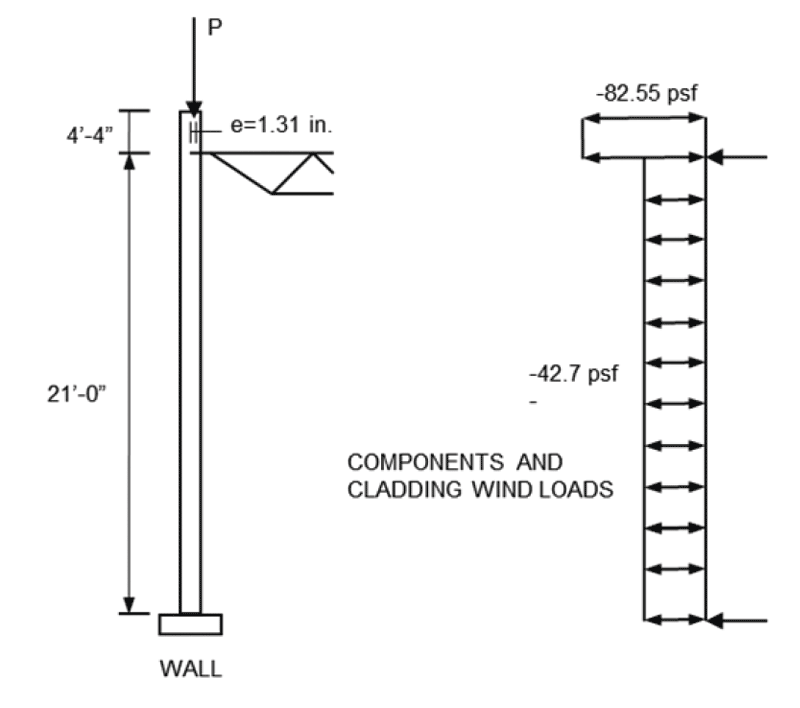
The following two examples show how the moment magnifier method can be applied to typical wall designs. The first case addresses a fully grouted 8-inch CMU wall, with PCL Type S mortar and a specified assembly compression stress (f’m) of 2000 psi, that is used to support a roof. The wall system is assumed to be reinforced with a Grade 60, #5 rebar, centered in the wall thickness at a 16-inch vertical spacing.
One critical loading condition on the wall is shown in Figure 1. The roof loading produces (1.2D + 1.6Lr + 0.5W), an axial load of 5,640 lb per foot of wall, and the maximum moment at mid-height of 1,210 lb-ft (14,600 lb-in) per foot of wall.
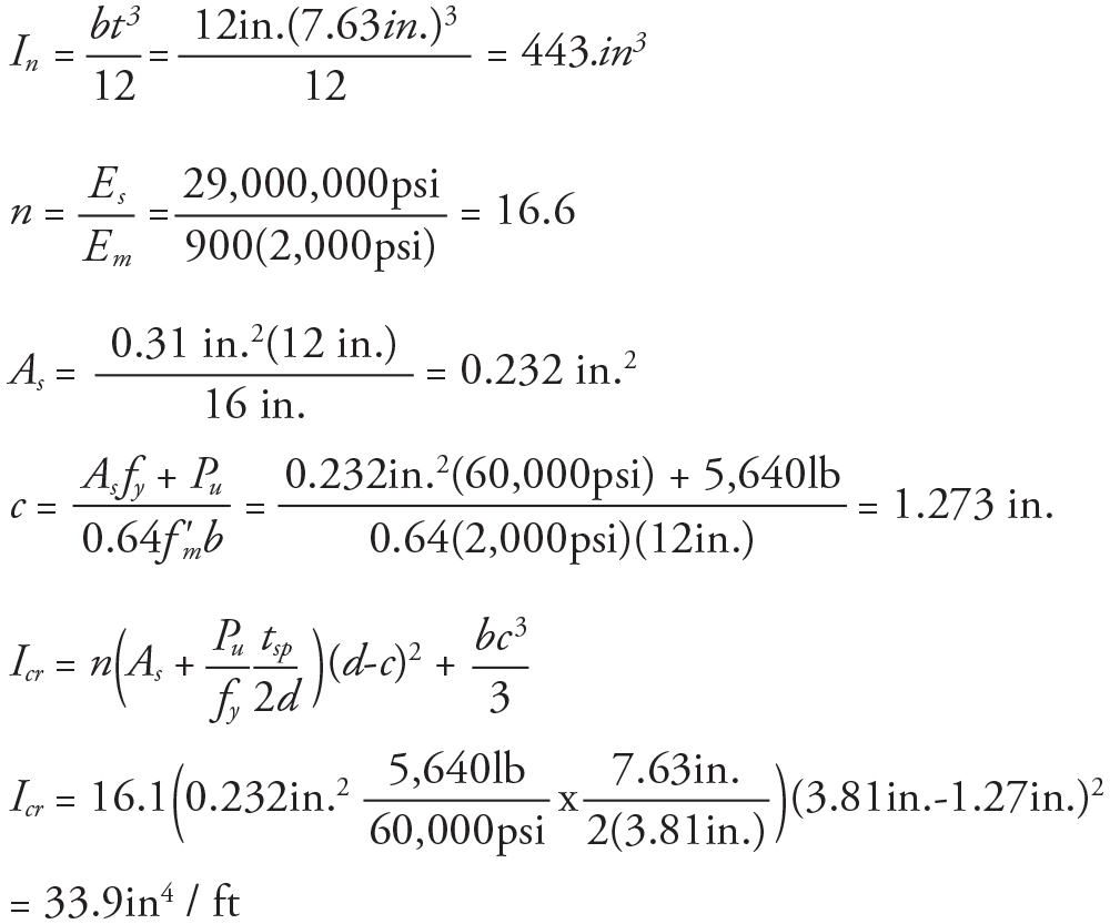
Using a 1-foot design width and the provisions in TMS 402, the net and cracked moments of inertia can be determined as follows.
A modulus of rupture (fr) of 163 psi was obtained from TMS 402 Table 9.1.9.2 for a fully grouted wall with Type S PCL mortar (normal to the bed joints). This produces a cracking moment for the given axial load as follows.
As required by the TMS 402 provisions, as Mu = 14,600 lb-in is less than Mcr = 26,100 lb-in then Ieff = 0.75 (In).
Thus,
and
This results in the design second-order moments of Mu = 1.06 (1,210 lb.ft per foot of wall) = 1,283 lb.ft per foot of wall.
The above calculations show the second-order effects only increase in the applied moments by 6% using the conservative moment magnifier analysis. As this level of loading and wall configuration are typical of most masonry wall systems, this increase due to second-order effects is also typical. It should be noted that second-order analysis need only be done for where vertical loads are applied to the walls and act to increase applied moments. Typically uplift due to wind loadings will act to reduce out-of-plane moments and need not be addressed.
Wall Section with Higher Moment
For the second example, a wall section with higher moments is addressed. In this example, it is assumed that a fully grouted, 8-inch CMU masonry wall is located below a lintel and subjected to a peak factored axial load of 2,000 lb per foot of wall and a maximum factored moment of 1,942 lb.ft (23,300 lb.in) per foot of wall. This wall section is also assumed to be simply supported over a height of 18 feet. The wall is constructed of masonry with an f’m of 2000 psi, with #5 rebar at 2 feet vertical spacing centered in the wall thickness.
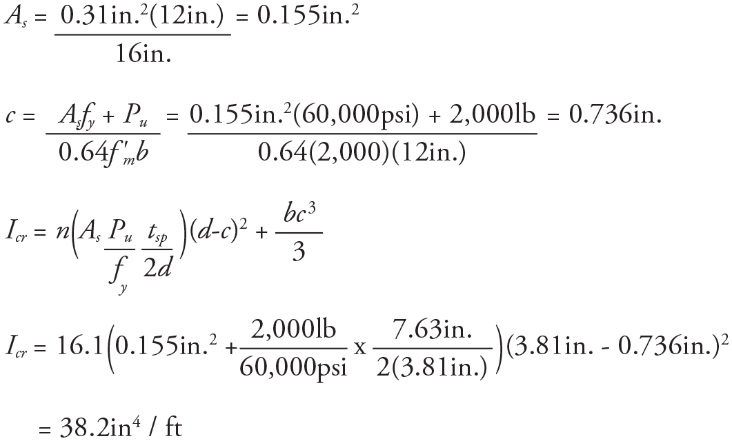
Using a 1-foot design width and the provisions in the TMS 402, the net and cracked moment of inertias can be determined as follows.
As before, fr is 163 psi (TMS 402 Table 9.1.9.2) for a fully grouted wall with Type S PCL mortar (normal to the bed joints). This produces a cracking moment for the given axial load
as follows.
Unlike the previous example, the Mu of 23,300 lb-in is greater that Mcr = 21,522 lb-in. Therefore, the standard provisions would require that Ieff be taken as = Icr.
Thus,
and
This would produce a design second-order moment of Mu = 1.16 (1,942 lb.ft per foot of wall) = 2,253 lb.ft per foot of wall.
The second-order effects in this second example were much higher than the first.
Summary
Examination of the equations used in the moment magnifier method shows that significant increases in second-order moments can occur when the applied moments exceed the cracking moment, and the applied forces are close to the Euler buckling capacity (Pe). This is more likely to happen with partially grouted walls with type N masonry cement mortars, as the fr and S values can be significantly reduced.
Also, where wall configurations and loading produce conditions where the cracking moment is exceeded and the axial force is close to the Euler buckling force, a significant reduction in predicted second-order effects are possible using the original slender wall procedures, as compared to the moment magnifier approach. This can be explained by examination of the TMS equation for the slender wall approach shown below.
In these provisions, when Mu is greater than Mcr (Eq. 9-30), only the portion of the applied moment above cracking is used to determine the deformation using Icr unlike moment magnification where Icr is essentially used to amplify all moments whenever the wall is subjected to moments higher than Mcr. Thus, second-order moment effects can be significantly reduced using the slender wall approach, which should promote its use if conditions warrant. Designers are encouraged, however, to use this new moment magnifier method as it provides simple, efficient procedures to conservatively estimate second-order moments and deflections for most masonry structures subjected to combined out-of-plane and vertical loads.▪


