
Drayton Hall is considered one of the finest, if not the finest, example of Palladian architecture in America (Figure 1). This 1740s plantation house sits on the banks of the Ashley River, near Charleston, South Carolina. It is owned by the National Trust for Historic Preservation and is maintained in roughly the same condition in which it was received from the Drayton family in the 1970s.
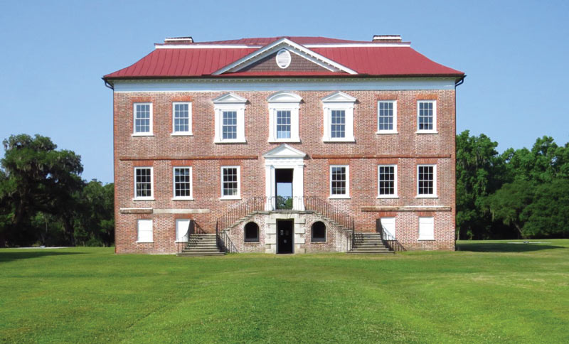
Figure 1. Drayton Hall.
The house was beautifully put together by skilled craftsmen when originally constructed. However, 270 years of weathering, numerous hurricanes, a major earthquake, and deterioration of materials have all left their marks on this majestic structure. Not surprisingly, some efforts to “fix” things have been less successful than others.
Over the last several years, it has been a privilege to both evaluate and design significant repairs to this National Historic Landmark. The lessons learned, or in some cases re-learned in doing this work, are especially valuable to all professionals doing maintenance and repairs on such historic structures.
As with most historic structures, work on Drayton Hall began with careful study. The design team was first asked to study the west, or land side, portico of the building (Figure 2) and to determine how serious a problem the deteriorating 1920s concrete supporting the first floor of the portico was. Following that study, the team did a general structural study of the whole building, focusing strongly on the effects of visitorship on the structure.
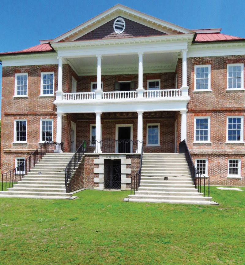
Figure 2. West Portico.
Study
These two initial studies had several interesting findings. The study of the portico showed that the columns were segmental columns of whitewashed limestone masonry. At the second floor, those columns supported brownstone lintels which themselves supported timber joists carrying a timber deck with a stone and concrete walking surface.
The first floor was much more interesting. The original timber structure had been replaced because of deterioration, once in timber and a second time, in the early 20th century, with a concrete beam and slab system supporting the brownstone and Portland stone pavers. Unfortunately, some of the concrete beams landed directly in the middle of the relatively flat 1740s brick masonry arches (Figure 3).
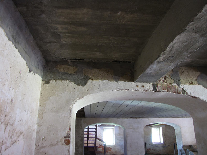
To make matters worse, the early 20th-century reinforcing was corroding and destroying those same masonry arches.
The study of the portico turned up a couple of other things that were relatively interesting. First, the brick piers that supported the arches appeared to have settled. Tracing the elevation of an original mortar joint on the wall above at the first floor showed that the columns beneath had settled just over 3 inches (Figure 4). This unquestionably indicated the need for both foundation investigation and load calculation.
Figure 4. Tracing a mortar joint to determine settlement.
Drayton Hall archaeologist Sarah Stroud carefully excavated the soil next to one of the footings. Her work showed that the footing stepped out only half the width of a brick, or two inches, all the way around. Calculation of the loading on the soil indicated that the bearing stress was roughly 6300 pounds per square foot, in an area normally designed for about 1500 psf. And that was just the dead load! Adding full live load resulted in bearing stresses up to about 9,000 psf. Typically this would seem to be a cause for immediate action. However, one must remember that the columns had been in this condition for roughly 270 years. The conclusion was that the settlement should be carefully monitored but that no immediate action need be taken.
Additional study of the portico showed that the two outermost columns were supported on tall masonry piers and that those piers had moved slightly away from the wall to which they had been originally attached. These two piers would have to be tied back to the wall and house so they could not move away from either.
While the portico had its share of problems, the house itself was generally in better shape, with the exception that the south wall was deformed outward. A simple laser scan confirmed that it had moved outward approximately three inches in the first ten feet from the ground floor to the first floor. Tying the south wall back to the house, particularly at the first-floor level, will be important in the future. It was deemed not as high a priority as was dealing with the damage to the 1740s brick masonry arches caused by the 1920s concrete.
Design
With the decision made that the 1920s concrete had to be removed, the question became, “What are the problems associated with doing so?” Further study of the portico indicated that the concrete slab, and even the beams, had been poured tight up under the stone columns. When determining how that could have been done without lifting the columns, it was ultimately concluded that the team did not want to know the answer to that question. Construction was significantly more risky in the early 20th century than it is today, and yet it had been done.
The task at hand was to determine a repair method. A simple 3D model of the structural system (Figure 5), without the concrete shown in place, indicated that removing the concrete would cause a tremendous stability issue.
Figure 5. Questionable stability of the columns if the concrete were to be moved.
It was clear that the stone columns would have to be lifted, but lifting more than a couple of millimeters risked breaking the stone lintels above and destabilizing the second-floor columns as well. So how should one lift a house of stone cards (Figure 6)? The decision–lift from the bottom, remove the concrete, rebuild the masonry, then insert a timber frame and deck to support a well-hidden modern drainage mat under the limestone and brownstone deck.
Figure 6. Segmental stone masonry – a potential house of cards.
Construction
The contractor for this delicate work was Richard Marks, who not only has a career of experience in historic preservation construction but has done graduate work in historic preservation at the University of Pennsylvania. Architect Glenn Keyes was instrumental in the design of what amounted to a plaza deck to support the stone pavers.
The first design for the shoring met with disapproval from the contractor – he was right…right for the wrong reasons, but still right. It was reengineered. Together, an agreement was made on a process to shore the columns off of the existing wall beneath them. This required significant investigation of the wall, then sequencing so that the masonry stayed stable at all times.
The sequence would be tricky:
- Cut away enough concrete to rebuild the masonry supports next to the columns, but still keep the structure stable;
- Rebuild enough masonry to provide support for the lifting mechanism;
- Let it cure;
- Lift the columns only enough to take the load off of the concrete under the columns;
- Remove the concrete under the columns and replace it with masonry;
- Lower the stone column back onto the rebuilt masonry; and,
- Install the timber joists, the deck, a waterproofing layer, a drainage mat and copper drains, a setting bed, a slip system, another setting bed, and finally the brownstone and Portland stone pavers.
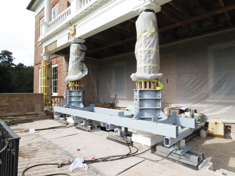
Figure 7. Lifting mechanism in place.
After reconstruction of the masonry wall on each side of the bases of the columns, the team was able to instrument the plinth blocks, then lift the columns, using the surrounding masonry (Figure 7) to get the load off of the masonry directly beneath the column bases. The first column was lifted 500 micrometers and the second only 200 micrometers. With the load off of the concrete, removal of the concrete beneath was easy, and reconstruction of the masonry under the bases proceeded (Figure 8).
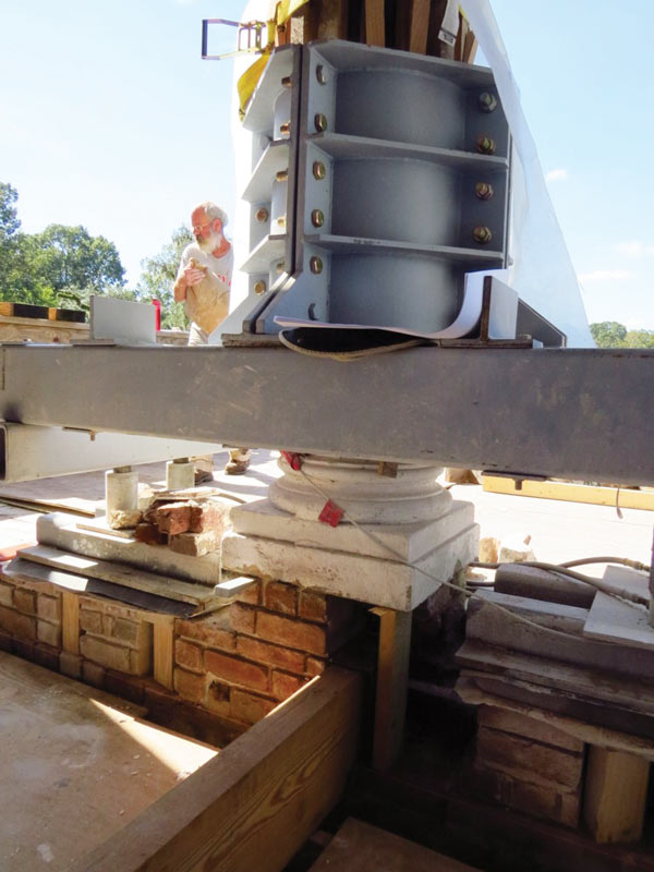
Figure 8. Freshly rebuilt masonry under a column base.
The masons were able to build joist pockets into the masonry wall and line them with copper boots to receive the ends of the timber joists (Figure 9).
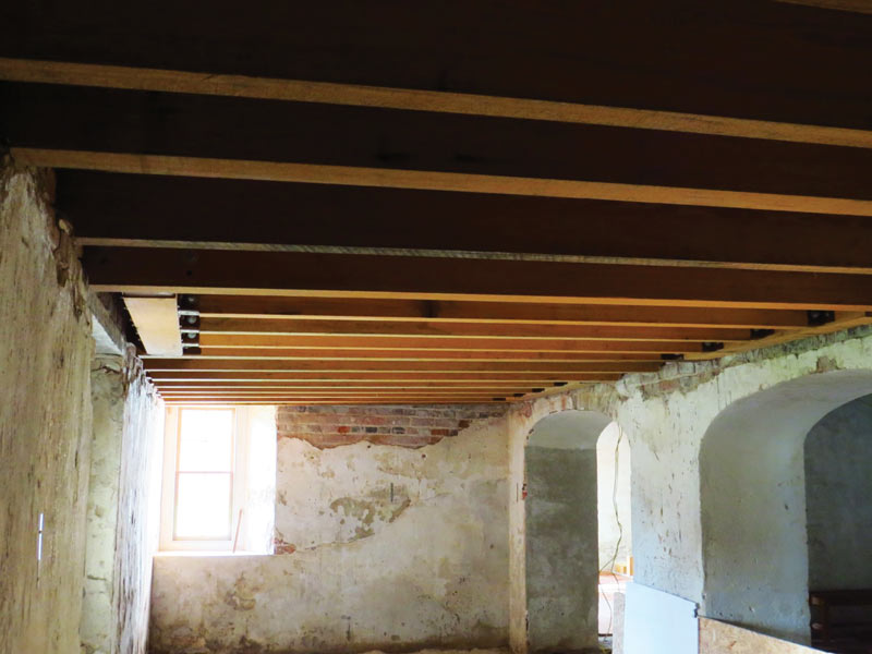
Figure 9. Timber joists taking loads to the sides of masonry arches.
The timber deck soon followed, as did all of the layers up to the stone pavers (Figure 10). The columns were lowered onto the cured masonry beneath their bases. The portico was ready for another hundred years.
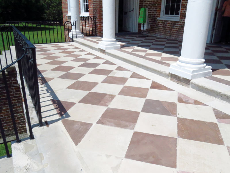
Figure 10. Rebuilt Portico floor.
Lessons Learned
For this job, it became apparent that the principles of working on historic structures were no different from those which are found in so many other structures from the eighteenth and nineteenth century. First and foremost, while Bennett Preservation Engineering was the prime design professional on the project, the work on such important structures is not the work of one person or even one firm. It is the work of a large team that includes other preservation engineers (Andrew Dutton in London), civil engineers, architects, archaeologists, historians, preservation contractors, and most important, an ownership team absolutely dedicated to historic preservation.
Other lessons were more mundane: it became acutely evident that later additions, such as 20th-century concrete, were not necessarily a good thing. While early 20th-century concrete holds up very well, early 20th-century rebar does not. It is also evident that the early 20th-century concrete was integrated very well into the 18th-century masonry, and that removing it had the potential to destabilize the whole structure. The team was further reminded that, as Jacques Heyman noted in his simple, clear primer on historic masonry, The Stone Skeleton, historic masonry is almost always controlled not by strength but by stability. Finally, there was a clear reminder that if you have to make a decision between saving 1740s masonry and 1920s concrete, go with the masonry.▪