
A bridge structure exposed to salt can expect corrosion of the embedded steel during its service life. Cathodic Protection (CP) has proven itself as the only permanent repair of existing corroded steel reinforced concrete. Therefore, CP must not be considered separately, but as a part of a complete rehabilitation program. (1993 Strategic Highways Research Program (SHRP) Report S-337)
Cathodic Protection (CP) is an electrochemical corrosion mitigation technique with origins dating back to 1824. Earlier though, in 1800, Alessandro Volta’s voltaic batteries were presented to the Royal Society, illustrating that electrical current was generated when metals with a different electro-potential were stacked together and separated with a cloth saturated in brine. It was Sir Humphrey Davy (Figure 1) who observed that the zinc electrode was corroded and the other electrodes, such as silver, gold, and copper, remained undamaged. Davy’s observations eventually led him to the concept of the electrochemical series of elements.
In 1806, Davy promoted his findings showing that copper in sea water was protected from corrosion when in contact with iron or zinc. Davy was able to apply his concept of electrochemical protection when, in 1823, he was ordered by the British Navy to assist with copper sheathing failures on wooden boats. Davy led the investigation into the rapid corrosion of Royal Navy ships’ hulls in sea water. His electrochemical cathodic protection system was applied to the HMS Samarang, which showed signs of corrosion after only three years in use. The system consisted of attaching four cast iron anodes on the hull: two on the stem and two on the bow, with a surface ratio of 1:80 of the copper surface. The attachment of the iron plates to copper sheathed wooden boats became standard practice in the British Navy after that. Eventually, zinc was used to protect steel hulls.

Figure 1. Sir Humphrey Davy.
The Evolution of Cathodic Protection
These early systems, based on the galvanic series of metals, utilized a metal with a more negative electro-potential to protect the more noble metal. Galvanic systems rely on the electrolysis of the metal following the laws established by Sir Michael Faraday in 1833. The oxidation of the ‘galvanic’ or sacrificial anode provides electrons at the cathode site where the reduction reaction or gain of electrons occurs. This protects the more noble metal. Like a battery, system requirements include an anode, a cathode, an electrolyte, and a metallic path. There is always a direct circuit between the anode and the cathode. The anode will eventually require replacement upon decomposition. While often erroneously referred to as ‘passive’ systems today, galvanic cathodic protection (GCP) systems do not rely on an external power supply.
Impressed Current Cathodic Protection Systems (ICCP), which depend on an external power source, have a younger history with late 19th century origins in the United Kingdom (UK). In referring to a corrosion problem of condensers in a power plant in 1919, Mr. M.J. Christie, of the Southwick Power Plant, chronicles the use of a Cumberland electrolytic system in the Journal of Electricity. He states that corrosion and the graphitization of the cast iron piping due to the use of sea water were the most far-reaching and significant concern for power users. He adds that his corrosion problems at the Southwick Power Plant were positively resolved when an electrolytic system was installed in the condensing systems.
From the 1920s forward, the use of ICCP was employed in buried structures such as pipelines, tank bottoms, and windmill foundations. By the 1950s, it was standard practice to use ICCP for the protection of any subgrade service carrying hazardous materials and cathodic protection was accepted as a means of corrosion mitigation. The earliest introduction of ICCP to protect reinforced concrete structures was in 1955 when it was used on concrete pipes.
The National Association of Corrosion Engineers was established in the United States in 1953. Cathodic Protection became an important means of preserving infrastructure, in large part because of the efforts of this organization to promote CP use.
ICCP System Components
The major components of Impressed Current Systems include:
- An external DC power source
- Anodes for current distribution
- Conductive electrolyte (concrete)
- Protective steel
- Wiring for circuit completion
- Monitoring system
Power supply units (PSUs) and main control unit (MCU) technology rapidly changes, as do means of communicating with systems.
Use of Cathodic Protection in Concrete Infrastructure
In 1959, the use of ICCP was demonstrated in concrete with the use of silicon iron anodes in reinforced concrete bridge decks. By the 1970s, full systems were installed in reinforced concrete. It was around this time when it was realized that concrete is an ionic conductor and can support a small amount of electrical current flow. The historical use of ICCP and its early development within bridge systems between the 1970s and the 1990s is well documented by the 1993 SHRP S-337 Report: Cathodic Protection of Reinforced Concrete Bridge Elements: A State of the Art Report. The Report noted: “This theory was first put into practice by R. F. Strafull and co-workers in the California Department of Transportation on the Sly Park Road Bridge in June 1973…The first bridge deck CP system installed by the California Department of Transportation (Caltrans) covered only a portion of the deck. After several years, the protected deck section was compared to the unprotected portion, and it was conclusively shown that the CP system prevented new delaminations from forming (except in epoxy-injected areas) and that the unprotected deck continued to deteriorate.” Similar studies were being performed in Canada and Europe with equal success.
The SHRP Report also cites a 1988-89 survey conducted by Battelle, the world’s largest independent, non-profit research and development organization, indicating that more than 275 bridge structures in the United States and Canada were currently cathodically protected. At that time, “the total concrete surface under cathodic protection was almost nine million square feet (840,000 square meters)…Most of the bridges were 20 to 35 years old when cathodic protection was applied. Ninety percent of the protected structures [were] located in deicing salt regions and 10 percent [were] in marine environments.”
ICCP and other corrosion mitigation strategies are often addressed when looking at critical structures which cannot be taken out of use, and when the cost and indirect impacts of replacing a structure greatly affect the owner, users, and local community. The 1990s and 2000s saw a proliferation of systems installed in Europe. The M4 motorway and Midland Links Projects in the UK were exploratory, essentially field programs that resulted in some of the largest ICCP system installations to date.
The concluding remarks of the SHRP report state that “a bridge structure exposed to salt can expect corrosion of the embedded steel during its service life. CP has proven itself as the only permanent repair of existing corroded steel reinforced concrete. Therefore, CP must not be considered separately, but as a part of a complete rehabilitation program.”
Impressed Current Cathodic Protection (ICCP) systems with Mixed Metal Oxide (MMO) sintered titanium anodes can have a design life of more than 50 years. “MMO anodes are a composite structure with valve metal substrate (titanium) covered by an electrocatalytic film of noble metal oxide. The anodes are characterized by very little dissolution of the metal oxide and uniform wear rates” (Kroon, et.al. 2007). The life of galvanic CP systems is finite, based upon metal consumption of the anode. Where embedded, galvanic systems still require replacement when consumed. Today, impressed current cathodic protection is commonly used on all reinforced concrete structure types (Figure 2), though the decision-making process for the correct system choice often needs to have a rationale and service life established by the design team.
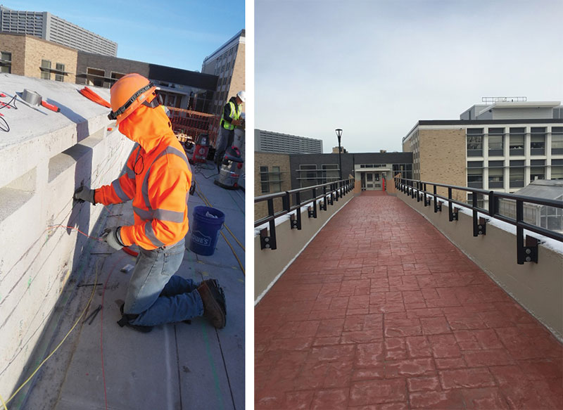
Figure 2. Left: Installation of an ICCP System on a pedestrian bridge. Probe MMO Ti anodes are installed on the parapet and slotted MMO Ti anode ribbon on the deck slab. Right: Pedestrian bridge after installation.
Decision Making Process for the Use of ICCP
Impressed Current Cathodic Protection Systems provide a significant service life extension for reinforced concrete structures. When choosing the correct system, the owner’s service life extension expectations must be established, as well as where the structure is within its lifecycle. To make the appropriate choice, the structure, and performance expectations, the designer must be aware of various conditions. Construction details, construction materials, contamination levels, anode output, steel protective current requirements, system operations, and distribution logistics are all required to ensure an appropriate design. Therefore, before designing a system, an in-depth analysis of the structure should be carried out and analyzed by a qualified team with experience in corrosion and material durability issues.
After determining the conditions which are driving corrosion and understanding the remaining service life, the investigator/designer should provide the owner with a system matrix based on the structure’s and owner’s requirements. This matrix should cover system types available for the structure, operational and maintenance requirements, and monitoring requirements. It needs to be established from the onset that ICCP Systems are not fit-and-forget system types. The success of a system after installation is based on on-going monitoring by a qualified professional. A life cycle cost for the system types, compared to traditional repairs, easily illustrates the value of higher one-time costs expended now to mitigate corrosion. This comparison highlights long-term protection versus future ongoing patching programs and continued corrosion which will eventually lead to the loss of structural integrity. An example of a repair matrix is shown in Table 1.
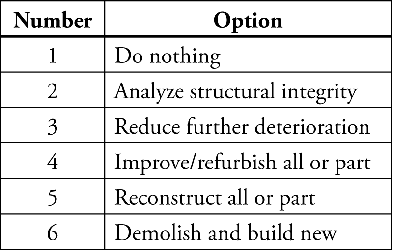
Table 1. Repair options.
As part of the further analysis of the appropriate system for any structure, the selection choice and rationale for repair can be further assessed by establishing owner requirements (Table 2).
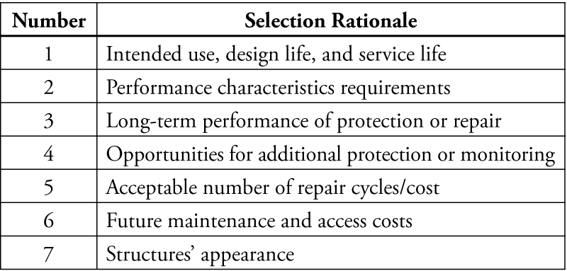
Table 2. Selection rationale.
Once requirements, desired service life, and work scope are established, corrosion control systems which fit the structure can be assessed. “Without a condition evaluation, and established rationale, the selection process for repairs [and corrosion mitigation] is difficult to achieve.” An example of the parameters established from a repair planning exercise for critical structures can be seen in Table 3. (See also Figure 3)
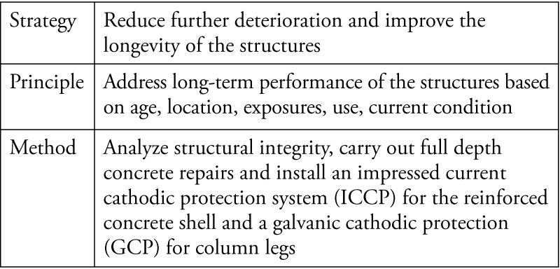
Table 3. Example of client repair rational.
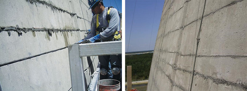
Figure 3. Installation of an ICCP System on a hyperbolic cooling tower with MMO Ti Ribbon.
System Types Available for Infrastructure Projects
Many anodes can be found on the market today, and some suppliers sell ‘systems.’ While there may be merit in compatible systems, the best practice is to perform an evaluation of the structure so that structure-specific systems can be designed. It is important that the correct material is selected for the long-term performance of a system (Table 4).
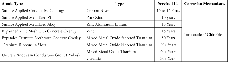
Table 4. ICCP anode types.
Upon selection of the optimal anode type, the system designer can commence with the design. All CP systems, irrespective of system type (i.e. GCP or ICCP) or anode material (Zn or MMO Ti), and anode type (coating, probe, mesh), should always be designed by qualified professionals who are not suppliers of material. Often, a material interest by a supplier influences design selection where other system types may provide a more optimal performance. Impressed current systems are the only systems which will provide long-term performance and also electrochemically alter the conditions surrounding the steel.
Case Studies
Many structure types are protected with ICCP, from transportation structures to critical infrastructure. The following case studies focus on a variety of structure types with long-serving systems in place.
Clyde Tunnel
One of the longest operating Cathodic Protection systems in service is the Impressed Current Cathodic Protection system installed in the Clyde Tunnel under the River Clyde in Glasgow, Scotland. The tunnel is 2460 feet (750 meters) long with 30-foot (9-meter) diameter twin bore tunnel tubes, each containing an elevated reinforced concrete deck roadway. Ongoing degradation and aggressive corrosion was impacting the embedded steel of the reinforced concrete deck
It was determined that the corrosion was accelerating as the road deck became contaminated by chlorides due to de-icing salts. There had been two previous repair contracts within the tunnel structure and both repairs had premature failures. The engineering and contracting team indicated that it would be prohibitively costly to remove and replace all the contaminated concrete using conventional methods. Investigations indicated that corrosion had occurred in the top-level reinforcing steel of the road deck, as well as the more visible soffit-level corrosion from under the roadway.
Before the final design, electrochemical repair techniques of chloride extraction (ECE) and ICCP were considered to minimize the extent of concrete removal. In 1994, a trial contract for CP was chosen over ECE to establish the effectiveness of ICCP using different types of anode systems and to assess how well they could protect the upper reinforcing steel. The resulting CP specification stated requirements for a design-and-construct ICCP system with a 25-year operating life. The work was completed in the West Tunnel before beginning in the East Tunnel. The installation program took two years to complete.
The design focused on protecting the concrete surrounding the 187 joints. For the length of the tunnel, approximately 4 feet (1.2 meters) of concrete and steel were protected on either side of the joints. The system involved the use of MMO Ti mesh and anode ribbons with a concrete overlay, with each joint acting as an independent zone. This system was the first distributed ICCP system installed in the UK.
In their 2015 Status and Options Report, the Glasgow City Council recommended the current ICCP system be upgraded as part of the Clyde Tunnel Assessment Renewal Program. This was identified as a high priority, to be installed within 1 to 3 years as the power supply system is nearing the end of its service life. At present, the Renewal Program does not list concrete repairs associated with corrosion of embedded reinforcing steel of the road deck because the ICCP system has mitigated any further damage since it was installed.
Midland Links
The Midland Links Motorway Viaducts (MLMV), which includes approximately 13 miles (21 kilometers) of elevated roadways, were the first reinforced concrete bridge structures in the UK to have electrochemical corrosion remediation systems installed. Across the entire MLMV, there are over 1300 spans, crossbeams, and expansion joints, and more than 3600 columns.
Over the years, however, the MLMV system has suffered from structural deterioration, primarily corrosion of the reinforcement owing to chloride attack.
Impressed Current Cathodic Protection systems were installed in more than 740 of the bridge structures in the Midland Links to mitigate corrosion. This work was pivotal in developing and refining ICCP systems for bridge structures. Based on these studies, ICCP is now commonly used worldwide for corrosion prevention and mitigation in bridge structures.
Summary
While these two case studies are based on UK systems which were installed in the early 1990s, they are used to illustrate the longevity and durability of the concrete repairs which include the use of ICCP for corrosion mitigation. It has been documented both by CONREPNET (the Concrete Repair Network overseen by the British Research Establishment) and the United States Army Corp of Engineers that concrete repairs typically have less than a 50% satisfactory performance rating. The following statistics are often used:
5 years – 80% of repairs are satisfactory
10 years – 30% of repairs are satisfactory
25 years – 10% of repairs are satisfactory
Cathodic protection was wholly successful in 60% of the installations reviewed; 20% required minor attention (80% functional) and 20% were nonfunctional. The review of the CP systems illustrated that there were minor faults in electrical mechanisms that lead to system malfunctions. All of these issues were easily rectified. With ICCP system designs, electrical components require 20-year replacement plans. Overall, the consensus of both programs was that properly installed concrete repairs, in conjunction with the installation of an Impressed Current Cathodic Protection System, provided the most durable and longest performing repair available.
More recently, the increased use of system energy plants for critical infrastructures, such as intake structures and cooling towers, illustrates their large scale use of ICCP systems. These projects not only provided cost savings; return-on-investment (ROI) studies illustrated that the impact to the local economy and owners would be in the range of 1.4 Billion USD and the cost of comprehensive repairs that included an ICCP component would equate to $80 Million USD. The owner opted for repair with ICCP in each of these instances.
With the staggering percentage of ailing infrastructure in the United States and the knowledge that corrosion grows exponentially, ICCP needs further consideration as a comprehensive mitigation tool to protect critical structures. The use of ICCP is well established in bridge and tunnel infrastructure, and should always be considered when owner expectations include extending service life, reducing future repair cycles, and minimizing life-cycle costs. Additionally, the use of ICCP as a sustainable and green system can be achieved by using solar powered systems.▪
References
Denison, I.A. “Contributions of Sir Humphry Davy to Cathodic Protection.” Corrosion Journal. Volume 3, Issue 6. 1947.
Cefracor CFPC. Protection Cathodique.
Christie, M.J. “To the Requirements of Large Power Stations.” The Journal of the Institute of Electrical Engineers. Volume 57, 1919.
Strategic Highways Research Program. Report Publication NO. SHRP-S-337. Cathodic Protection of Reinforced Concrete Bridge Elements: State of the Art Report. 1993.
Kroon, D. and L. Earnes. MMO Coated Titanium Anodes for Cathodic Protection. National Association of Corrosion Engineers (NACE) CORROSION 2007. Conference Paper No. 07045
Noyce, P. and A. Hite. Selection of Corrosion Mitigation System for Two Reinforced Concrete Hyperbolic Cooling Towers in a Marine Environment. NACE 2010 Conference and Expo. Conference Paper NO. 10126. March 2010.