
Engineers knew for years that making spans continuous over piers could save a significant amount of wood, iron, or steel over that required for a series of simple span bridges. In fact, wooden bridge builders like Timothy Palmer, Theodore Burr, Ithiel Towne, Stephen Harriman Long, and others frequently built their spans continuous over the piers. They had only their intuition and experience to arrive at a design. Long, however, gave the matter serious thought and wrote about it in his pamphlet on bridge building, Directions to Builders of the Jackson Bridge. In it, Long gives the first indication that he indeed does have some “approved rules” for designing a continuous bridge. For the upper and lower chords he wrote:
“…they should be equal to each other in their transverse dimensions and initial strength. …wherein …the perfection of the plan of construction before us, consists in such an arrangement of the strings as will subject them to equal action in sustaining a load upon the bridge.”
He said that this was to be accomplished by:
“…rendering the upper strings continuous, over the piers and abutments, in such a manner that a degree of tension may be exerted at those points equal to that exerted by the lower string, at points intermediate to the spans, and vice versa, that the degree of thrust exerted by the lower strings against the piers and abutments, may be equal to that exerted by the upper strings, at the intermediate points as above.”
In other words, he made his trusses continuous over the intermediate supports so that the maximum negative moment over the support is equal, or nearly so, to the maximum positive moment located between the supports. He continued:
“…the reciprocity of the actions of the upper and lower strings, here adverted to should be aimed at in all bridges whose spans exceed 120 or 130 feet; but need not be particularly regarded in bridges of less extent: inasmuch, as the tension in the lower, and the thrust in the upper strings, may be effectually counteracted without increasing the dimensions of the pieces to an unwieldy size.”
To achieve this equality of load in the upper and lower chords he wrote:
“…in dividing the breath of a river into spans for a bridge, except the exterior spans, or those contiguous to the contemplated abutments, which should have only about three-fourths the extent of the other spans. The reason for this will be obvious from a recurrence to the principle of double action in the strings…the centre posts of the truss frames for the exterior spans must be located not at the centre of the spans, but at a point distant from the abutment about 1/3 part of the length of the exterior span.”
As a result of this experimentation, the effect of continuity on the stiffness of beams was known intuitively for some time. Robert Stephenson built his famous tubular bridge across the Menai Straits in Wales continuous over three central piers in March 1850. However, no one in the United States, or for that matter in Europe, had developed an analytical method for determining the reactions of a continuous beam, the moments over the piers, or the maximum moment between the supports until the Theorem of Three Moments was developed by Benoit Clapeyron in 1857. The Theorem was updated by Mohr in 1860 to include settlements of the supports. These equations, however, included a value for the modulus of elasticity, E, and moment of inertia, I, of each span and normally did not permit any settlement of the piers that could increase the moments the spans would have to resist. The assumption that E and I were constant over all the spans reduced the complexity of the equations, making it easier to determine the moments over the piers and thus the reactions. With reactions known, the moment at any point along the spans could be identified and the member sized appropriately. Some engineers also worried about the effect of temperature changes on the member loads and stresses.
The reason many engineers did not use continuous spans was that, at the time, they had little confidence that E was constant nor that I was constant over the length of the spans. They also worried that any settlement would add to the moments the spans would have to resist. These factors were taken into consideration by C. Shaler Smith (STRUCTURE, August 2008) when he was called to design a railroad bridge across the St. Lawrence River at the Lachine Rapids near Montreal. Smith had already built his famous Kentucky High Bridge (STRUCTURE, August 2015) as a continuous truss during erection but, by cutting the lower chords at two points, he converted it into a cantilever truss. The fact that the base of the river was solid rock eliminated, in his mind, the settlement problem. This would be Smith’s last major bridge project, built for the Canadian Pacific Railroad looking to extend its line to the east and across the St. Lawrence River near Montreal in January 1882.
The first bridge plan proposed consisted of “ten deck spans of 300 feet in the clear and one through span of 330 feet with a clear headway of 60 feet above ordinary summer water. The bottoms of the deck spans were placed 30 feet above ordinary summer water.” The bridge would cross the Lachine Canal and the Grand Trunk Railway, as well as the St. Lawrence River just upstream from the Lachine Rapids. A revised plan was submitted to the government “with 12 spans of 250 feet and one of 330 feet.” This was not satisfactory with the river men, mainly those who ran log rafts down the river, so the Chief Engineer for the railroad, P. Alexander Peterson, agreed to a plan with “11 spans of 268 feet and one span of 340 feet.” It was not until the summer of 1884 that Peterson called in C. Shaler Smith as consulting engineer. Upon reviewing the site, he was worried about building piers in the St. Lawrence and proposed “there should be introduced two spans of 258 feet and two spans of 408 feet over the channel, thus getting rid of one deep water pier, and probably one years time in the construction of the bridge.” The two 408-foot spans would be erected on the cantilever principle with 258-foot spans serving as anchor spans.
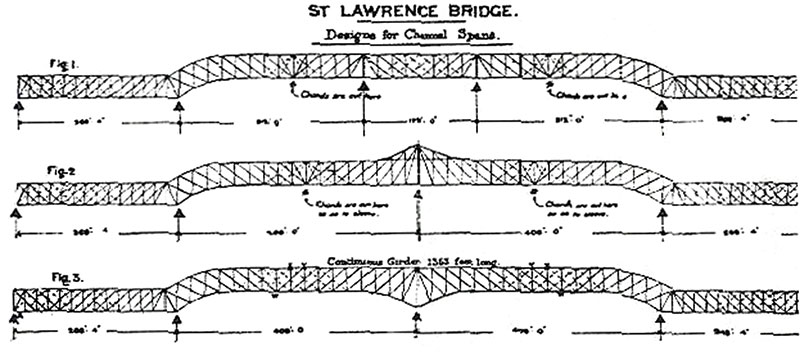
Smith’s proposed designs.
Smith considered three schemes of building the channel spans (see diagram). The top plan was for a bridge with two piers in the main channel and pins inserted at points of contra flexure, making it a cantilever with all reactions determinate. The middle plan was for a single pier in the main channel and pins again inserted in the lower chords and a top chord peaking over the center span, making it also a cantilever with all forces determinate. The last alternative was selected with the 408-foot spans and flanking 269-foot 10-inch spans being continuous.
Smith decided to build a continuous truss saying, “when the connection is made in the centers of the cantilever spans, the joints are to be riveted up so that they will act as cantilevers for dead load and as continuous girders for live load.” All expansion and contraction movements were to be taken up in the ends of the flanking or anchor arms that were on rollers or rockers with tension links holding down the ends during the cantilevering process.
Tenders (proposals) were called for in September 1885 on two different plans. A complete specification for the bridge contained a section on span length, which stated:
“The plans show the piers of the bridge over the St. Lawrence arranged in two different ways; No. 1 arrangement has eight spans of 242 feet center to center of piers, two spans of 269 feet 10 inches center to center, and two spans of 408 feet. No. 2 arrangement has nine spans of 268 feet, two spans of 269 feet, and one span of 340 feet center to center: but tenders and plans will be received for any other arrangement providing the position of the east pier of the channel span was not changed, and that no piers were placed closer than 242 feet center to center.”
Plan No. 1 was adopted, and the erection process on the four central spans consisted of first building the 269-foot 10-inch anchor spans on falsework. The channel spans were then cantilevered out 10 panels from each anchor span using conventional techniques. The new twist in the erection was to build cantilevers out each way from the central pier. This “was known in Mr. Smith’s office as the ‘Flying Cantilever,’ and was first proposed for the Storm King Bridge over the Hudson River, in the State of New York.” A short, temporary falsework was built from the central pier to support the first panel point in each direction. After the construction of these two panels, the spans were built out equally with a traveler moving in each direction and great care taken to keep the spans in balance. Also, cables were strung from the completed cantilevered spans to help maintain the central portion in a stable position throughout the construction of the eight closing panels.
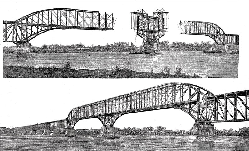
Lachine Rapids Bridge under construction and completed.
The single track bridge was completed successfully and opened to traffic in July 1886. The trusses were Whipple Double Intersection and pin connected. The appearance of the bridge created a great deal of discussion in the journals of the day. The Railroad Gazette reported:
“There are a great number of such combinations of through and deck span throughout the country, and surely will be more. Their ugliness results, of course, from the sharp break in the continuity of the lines of the structure, which destroys all dignity and pleasing effect, and gives them a flimsy and makeshift look. Whether giving to the through spans the form of a bastard arch which is not an arch is any real remedy may plausibly be disputed, but we are inclined to think that the design shown will be generally considered a more pleasing, or rather less ugly, solution of the problem than the ordinary form, and so, on this ground alone, worthy of use in such localities.”
It was erected by the Dominium Bridge Company under the leadership of Job Abbot (STRUCTURE, April 2012). Smith was virtually on his deathbed during bridge construction and died shortly after its opening on December 19, 1886. For 29 years, it was the only major continuous bridge in the America’s. Many engineers were still reluctant to believe that the savings in iron and steel were high enough to risk the increases in loads and stresses in the truss members due to the unknown possible effects of variations in E, I, the settlement of foundations, and temperature.
The bridge was replaced in 1913, due to increased loading, with two parallel simple span bridges each carrying one track. Since it was not possible to stop traffic during construction, they expanded most of the piers downstream and built a new single track bridge on the expanded piers. This was followed by removing the old bridge spans and building another single track bridge on the existing portion of the piers.▪