
Wind-induced vibration is an ever-present issue in lighting support design. It can cause seemingly magical movement of lighting poles, even when no storm or extreme wind event is present. Engineers recognize this “pole dance” as resonance. When there is too much of it at high amplitudes of deformation, the structure has a high likelihood of failing.
Typical low-level lighting poles are under 50 feet tall, can range from 4 to 12 inches in diameter, and have wall thicknesses between 1/8 inch to 3/8 inch. These poles are typically manufactured out of aluminum, steel, fiberglass, or concrete, and can come in various shapes – round, round tapered, square, multi-sided, and fluted. The focus of this article is primarily on aluminum and steel poles.
The most common document for lighting pole design is the Standard Specifications for Structural Supports for Highway Signs, Luminaires, and Traffic Signals (commonly known as the LTS), published by the American Association of State Highway and Transportation Officials (AASHTO). This specification uses typical structural analysis and design concepts for the design of poles and includes a section on fatigue design. AASHTO LTS utilizes ASCE 7 wind maps and general wind pressure equations and variables for design wind loads. In the AASHTO LTS, the wind pressure variables such as drag coefficients and gust factors are tailor-made for slender, flexible structures such as poles and sign posts, whereas these types of structures are generally outside the scope of ASCE 7. However, there is little guidance in the LTS on the use of damping as an effective vibration mitigation device. In general, the fatigue criteria in the LTS are used to examine the fatigue resistance of pole aspects by comparing stresses potentially generated by several types of wind-induced vibration (natural wind gusts, vortex shedding, galloping, etc.) with a constant-amplitude fatigue limit (CAFL). The fatigue criteria in LTS are not required to be used for low-level luminaire and sign supports, although there has been some interest in making the fatigue requirements apply for all poles, regardless of size. It is believed that, with proper damping, the majority of motion issues in low-level pole-type structures could be resolved. The typical remedy to a design that does not meet the fatigue requirements is to increase the size and stiffness of the pole to meet the requirements, as needed. This could create significantly over-designed poles for strength just to meet the fatigue requirements. Increasing stiffness may solve a motion issue in a particular mode of vibration. However, by increasing the pole’s natural frequencies, another mode of oscillation may be excited with sufficient wind energy and cause damage; whereas before, the wind energy input in that mode was minimal.
Wind-induced vibration is typically a site-specific phenomenon that is difficult to predict. Both steady, constant winds and periodic wind gusts can set up a resonance in a pole in various modes of vibration. Figure 1 gives the most common modes of vibration seen in service for low-level lighting poles with post-top luminaires, although higher modes of vibration have been known to occur.
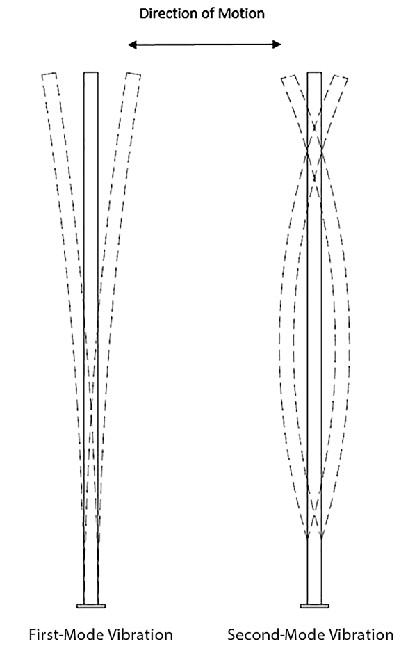
Figure 1. Approximate first- and second-mode shapes.
First-mode vibration is commonly described by a swaying motion of the pole with the maximum amplitude at the top, while second-mode vibration can usually be described by an “S”-shape, with the maximum amplitude somewhere near two-thirds the height of the structure. Given enough cycles, both modes can be damaging if the amplitudes are high enough, generating sufficient stress that the material or welds begin to fatigue and crack even though the entire pole was designed adequately for strength. Different conditions, however, tend to excite these various modes. First-mode oscillation is excited by gusty winds where the pole’s motion becomes locked-in with the wind gusts. Second-mode oscillation is caused by a steady, constant wind that creates vortices in the along-wind direction of the pole, causing movement perpendicular to the wind direction due to vortex shedding. First-mode oscillation can also be brought on by vortex shedding, albeit for poles with higher fundamental frequencies. Through experience, it has been found that certain types of poles are more prone to wind-induced vibration than others. They are shown in Figure 2.
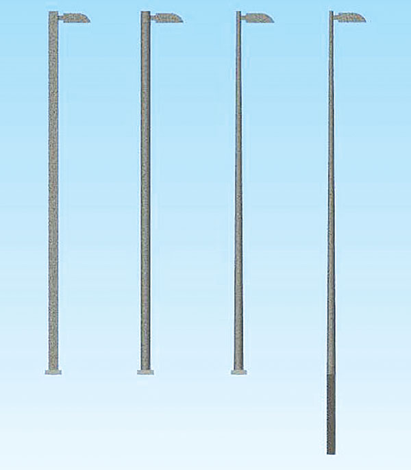
Figure 2. Vibration tendency, highest to lowest: straight square, straight round, round tapered, round tapered embedded.
Typically, constant diameter poles, such as straight round or square, have the greatest tendency to be affected by wind-induced vibration due to less ability to disrupt the vortices created by a steady-flowing wind. Tapered poles have a constantly changing diameter that provides less of a chance for vortex shedding lock-in to occur. Resonance set up by periodic wind gusts can occur on the majority of pole types in Figure 2. Most embedded poles are often provided a sufficient amount of damping by the earth they are embedded in, and typically see little issue with vibration. In addition to the pole shape and size, luminaire shape and size also play a major role in determining whether a pole assembly may become resonant or not. Thin, small luminaires (think airplane wings) have a low projected area and are essentially like not having a luminaire at all – this takes away from the vortex-disrupting turbulence that a luminaire can provide. It has been found that if a pole is installed without a luminaire, it has a higher chance of becoming resonant.
In recent years, there have been documented cases of pole-type structures in service that were designed to the fatigue requirements of LTS and experienced harmful resonance, suggesting that simply increasing the stiffness to get out of a range of resonance is not the best answer to solving a potential motion problem. Another course of action, and a tried and true method, is impact damping.
Impact dampers typically consist of some mass that physically contacts a surface in a repeated fashion, as often as needed, to attenuate motion. The quantity of mass can be tuned (most often added) to match the damping requirements of the structure. Some typical impact dampers and their mode of effective attenuation are presented in Figure 3.
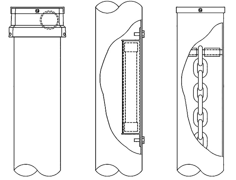
Figure 3. Damper sketches, left-to-right: first-mode damper, second-mode damper, first-mode damper.
Various forms of the devices in Figure 3 have been around for decades. The first device is essentially a ball in a box and counteracts first-mode vibration, the second device is a rod in a canister and counteracts second-mode vibration, and the third device is a hanging chain and counteracts first-mode vibration. These are placed at the location of expected maximum amplitude of the target mode. As the mass collides with the sides of its “container,” whether that be the pole itself or another device, the impact causes a disruption in the resonance of the structure and helps to absorb some of the resonant energy of motion. With enough collisions, the structure can be effectively dampened to acceptable amplitude levels. For the second-mode damper, the rod is in close proximity to its containment structure – this is necessary because of the low amplitudes and higher frequencies (meaning more rapid stress reversals) associated with this mode of vibration. A larger separation for a second-mode damper, such as for first-mode dampers, would prove ineffective, as the mass would rarely, if ever, contact the sides of the container.
The chain dampers go inside the pole at the top and are attached using a through-bolt with spacers or are hung from a pole cap. They are encased in a PVC hose and their impacts are not detrimental to the structural integrity of the pole; however, they should not be used where wiring is located near the top of the pole, as the chain could interfere with the wiring. The lead ball damper is attached at the top of the pole using set screws. The lead ball is epoxy-coated, and the lead helps to absorb some of the resonant energy through local deformations. These deformations are small and it is believed do not significantly degrade the performance of the damper over time, although no relatively long-term studies are known to have been conducted. The second-mode damper is placed inside the pole and is typically recognized by 2 bolts protruding on the outside of the pole. Most any of the damping devices presented herein can be retrofitted on existing poles. The cost of a typical damping device such as those presented in this article can range from 1% to 15% of the cost of the pole, depending on pole size. Inspecting the elements of a damping system should be part of a routine pole maintenance schedule to ensure their proper function. A photograph of these devices is presented in Figure 4.
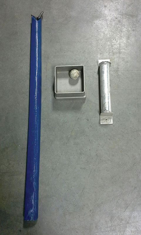
Figure 4. Dampers, left-to-right: hanging chain first-mode damper, lead ball first-mode damper, canister second-mode damper.
An example of the degree of damping that a small amount of mass can provide is presented in Figure 5. All graphs give the amplitude versus time from full-scale tests on a lighting pole undergoing free vibration from a pluck test in a motion that is synonymous with first-mode vibration. The subject pole is a 23-foot-long, 6-inch diameter by a 5/32-inch wall aluminum pole with a 50-pound mass attached to the top. The graphs were truncated when the amplitude dropped below about ½ inch. In Graph #1, the pole went through approximately 500 oscillations before the amplitude at the end of the pole dropped below a ½ inch. Graphs #2 to #4 are the same pole plucked at the same maximum amplitude, with varying degrees of damping that include multiples of a 2-pound lead ball. For this particular pole, a small amount of mass in an impact damper causes the number of oscillations to drop from around 500 for an undamped system to around 60 for one ball, and down to approximately 20 with 4 balls (the damper boxes can be stacked). In this situation, one can see that there are diminishing returns as the amount of mass in the damper increases. The abrupt change in slope of graphs #2 thru #4 gives an indication that the pole’s amplitude was low enough that the ball no longer impacted the container. It can be seen that impact damping considerably reduces the number of oscillations that a structure undergoes after the damping is initialized, and can quickly reduce the amplitude, and thus the stress range, experienced by the pole.
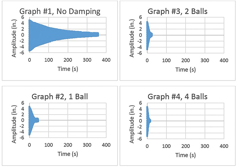
Figure 5. Amplitude vs. time for a first-mode damper system.
Wind behavior on structures can be difficult to understand – even more so when it becomes apparent that a slight geometry change or change in natural frequencies can be the difference between a lighting pole structure undergoing harmful resonance or not moving at all. Instead of over-designing the structure for increased stiffness, a more cost-effective way to mitigate vibration is to utilize mass/impact dampers – which have been used effectively for decades and can be tuned for sight-specific conditions by adding more mass. Dampers are not a “cure-all,” but they do solve the majority of motion issues due to wind in low-level lighting. Damping can be an often misunderstood, proprietary concoction of fluids, weights, shapes, etc., or it can be as simple in construction as an impact damper. The next time a low-level lighting pole design is in order and resonance is a potential issue, consider damping as a method of vibration mitigation and for providing a longer fatigue life for your structure.▪
References
AASHTO. 2009. Standard Specifications for Structural Supports for Highway Signs, Luminaires, and Traffic Signals. 5th Edition. American Association of State Highway and Transportation Officials, Washington, D.C.
ASCE. 2006. Minimum Design Loads for Buildings and Other Structures. Report No. ASCE/SEI 7-05. American Society of Civil Engineers, Reston, VA.
May, J., Menzemer, C. Nonlinear Vibration Control of Long Flexible Structures Employing Inter-Modal Energy Transfer (Modal Damping). Journal of Vibration and Control, September 2010. Vol. 17, 10 pp. 1557-1566.