
Soft-Story Retrofit Solutions
Recent natural events have provided material evidence of the social and economic impact to large metropolitan areas when a city is not prepared or lacks a robust recovery plan. More than 230,000 people migrated from New Orleans within the first nine months after Hurricane Katrina. The census data showed only 100,000 returned within the following eight years. The 6.3 magnitude earthquake in Christchurch, New Zealand, in 2011 damaged 70% of the central business district (CBD). Most buildings were deemed too dangerous to occupy. In response, all the buildings in the CBD were closed due to concerns about aftershocks.
Many highly populated cities along the West Coast in the United States are vulnerable to this same fate. These cities consist predominantly of wood-framed residential and multi-family apartment structures. Structures of concern are commonly three or more stories in height with ground-floor levels consisting of open storefronts, garages, or tuck-under parking. This type of building is referred to as a soft-story structure. Thousands of these buildings were constructed to codes which, at that time, did not adequately account for this vertical irregularity. Non-ductile materials and finishes, with low displacement capacities, were often used to provide lateral resistance. Subsequent evidence has revealed that soft-story structures are susceptible to collapse, as observed during the 1989 Loma Prieta and 1994 Northridge earthquakes, and in NEES-Soft Project research and testing conducted at the University of California, San Diego.
Strengthening of buildings with a high potential of risk of significant damage is one way cities are investing in the preservation of their unique character. In the 1980s, the City of Los Angeles implemented an ordinance requiring owners of unreinforced masonry (URM) structures to strengthen their buildings. The realization of that ordinance was evident in the minimal injury from URM building collapses after the 1994 Northridge earthquake. Most recently, cities like San Francisco, Berkeley, and Los Angeles have put in place mandatory retrofit programs for soft-story structures permitted or built before 1978. More cities are currently investing in a plan to adopt similar programs to increase the resiliency of their communities. Typical seismic retrofit methods include using conventionally framed wood shear walls or moment frames to add strength and ductility to the structure. This article focuses on the use of moment frames.
Moment frame assemblies are configurations of beams and columns designed to transfer the bending moment and shear forces through the members and connections to provide resistance to lateral forces. When a moment frame is used to provide the additional strength without obstructing openings, engineers can select one of three types; ordinary moment frames (OMF), intermediate moment frames (IMF), and special moment frames (SMF). The expected performances of the beam to column connection define the classification differences.
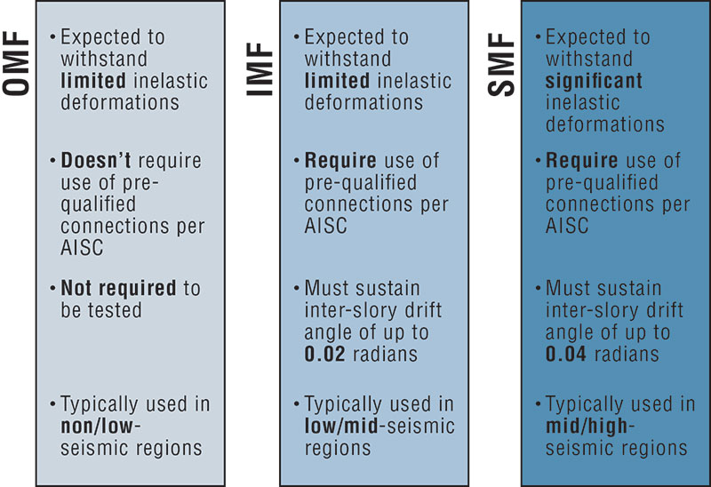
Comparison of moment frame connection types.
AISC 358 Prequalification
Seismic Provisions for Structural Steel Buildings (ANSI/AISC 341) provides a guideline for the design of moment frames. Prequalified steel moment connections are published in the Prequalified Connections for Special and Intermediate Steel Moment Frames for Seismic Applications (ANSI/AISC 358). Where SMF are used, the design of the moment connection needs to meet the performance criteria in AISC 341, or follow the prequalified connection and detailing requirements in AISC 358. Prequalified moment connections are a specific steel moment connection configuration and details that the AISC Connection Prequalification Review Panel have reviewed to meet the performance criteria for an SMF and incorporated into the AISC 358 standard. AISC 341-10 Seismic Provision provides the cyclic testing program to measure the performance of a moment connection. A connection must achieve a minimum joint rotation of 0.04 radians with at least 0.8 Mp of the measured flexural resistance as one of the criteria for meeting the SMF requirements.
Traditional SMF are designed with the beam yielding under large displacement. The yielding of the beam section provides energy dissipation and is designed to ensure the connection between the beam and the column is not compromised. The current design philosophy is the product of extensive testing of SMF connections after the 1994 Northridge earthquake in California. SMF are required to have the resilience to withstand large rotation of the connection between the column and beam. The beam must be stabilized using bracing to keep the beam compression flange from buckling when a plastic hinge is formed.

Beam deformation of RBS connection at the plastic hinge.
Beam Bracing
SMF are expected to withstand significant inelastic deformation during a design earthquake. Typically, bracing at specific locations is required to stabilize the beam from lateral torsional buckling observed under large displacements. Section D1.2b of AISC 341-10 provides beam bracing requirements to prevent undesirable beam buckling failure modes that may occur during the formation of plastic hinges in the beam. In AISC 341-10 Section D1.2b, “Bracing of highly ductile beam members shall have a maximum spacing of Lb = 0.086ryE/Fy.” Special bracing at plastic hinge locations requires both flanges of beams to be laterally braced or the member cross section torsionally braced. Bracing needs to satisfy minimum stiffness and strength requirements. Requirements for SMF stability bracing of beams are summarized in AISC 341-10 Section E3.4b.
In structural steel buildings, additional steel beams connected to full-depth shear tabs with slip-critical bolts have little difficulty in satisfying SMF bracing strength and stiffness requirements. Meeting the code-prescribed SMF bracing requirements is far more challenging in wood light-framed structures due to the relatively low strength and stiffness of wood compared to steel. Oversized holes in the wood, vertical deflection of the floor beam, and horizontal deflection of the floor diaphragm are some of the sources of deflection making it challenging to achieve the minimum bracing stiffness AISC mandates for an SMF.
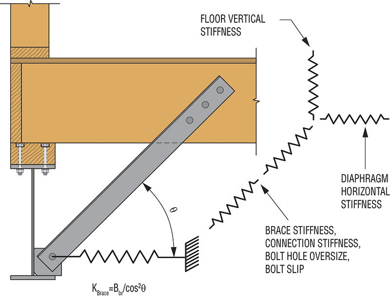
Stiffness model of beam stability bracing in wood construction.
AISC 358-16, Chapter 12
To address the design challenges with beam bracing and avoid field welding in wood light-frame structures, Simpson Strong-Tie® developed a field-bolted, partially restrained (Type PR) moment connection. The solution uses a patented Yield-Link™ structural fuse design to provide the moment connection. The unique capacity-based approach of the Yield-Link design represents a departure from traditional moment frame connections in two notable ways.
- The energy-dissipating Yield-Links can be replaced similar to a “fuse” in an electrical system after a major event.
- The beam and column members are designed to remain elastic. This allows the beam to be designed with no SMF requirements for stability bracing of beams.
The soon to be released AISC 358-16 edition of Prequalified Connections for Special and Intermediate Steel Moment Frames for Seismic Applications will include Simpson Strong-Tie moment connections in Chapter 12 for special and intermediate steel moment frames. The traditional beam yielding mechanism for a moment frame is eliminated from the beam and isolated to the replaceable Yield-Link element. The Yield-Link fuses are bolted in the shop using twist-off-type tension-controlled (T/C) bolts. A buckling-restraint plate (BRP) is bolted over the reduced region (stem) of the Yield-Link. The shear tab includes horizontally slotted top and bottom holes to minimize load transfer from the beam to the column. All shop welds and T/C bolt installations are inspected by a third party. Field installation permits the use of ASTM A325 bolts installed snug-tight at the Yield-Links-to-column and shear plate connection. Cyclic and full-scale shake table testing confirmed the use of snug-tight field-installed bolts along with no SMF requirements for beam flange bracing.
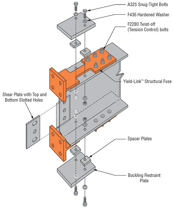
Factory installed Strong Frame Yield-Link™ Structural Fuse Special Moment Frame Joint.
The frame reflects a true capacity-based design approach that allows the connection to remain elastic under factored load combinations, with inelastic rotation demand confined within the Yield-Link. Under large displacement, the stem of the Yield-Link fuse is expected to yield in both tension and compression. The BRP, along with spacer plates, prevents the stem from buckling under compression cycles. The beam and column member design is based on the maximum rupture strength (Pr_link) of the stem of the link. Since the rupture strength for a given Yield-Link structural fuse remains constant, the beam and column can be checked to ensure the connection strength does not exceed the elastic limit of the frame members. Full-scale cyclic frame tests consistently demonstrate the high ductility capacity of the system, often reaching and exceeding a story drift angle of 0.06 radians. The Strong Frame SMF connection has successfully demonstrated the ability to meet or exceed the AISC prequalification requirements.
Typical One-Story Moment Frames
A wide variety of projects – ranging from single-level frames, under these mandatory retrofit programs, to multi-level and multi-bay frames in voluntary retrofits and new construction – have benefited from this innovative solution. Single-level frames are common, as many of these ordinances focus the retrofit effort on the first level. In high-occupancy structures with multiple tenants and limited parking space, it is necessary to minimize the time and encroachment during construction. Tenants can continue to occupy the units during construction as the all-bolted Strong Frame SMF requires no onsite welding. Projects are not delayed for welding inspection, installation time and effort is reduced, and risk of fire associated with welding during erection is eliminated.
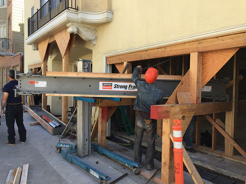
Frame installation where beam is maneuvered into place before bolting together for soft-story retrofit.
In many cases of retrofit design, it is necessary to provide access to the frame on the interior of the structure in tight quarters. A bolted frame solution allows the beam and columns to be assembled in parts. This reduces demolition that might otherwise be required for a preassembled frame and allows easy integration into the project’s construction schedule. Architectural impact and labor cost in installation are significantly reduced with the elimination of beam bracing.
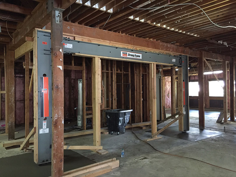
Installed moment frame for retrofit of the light-frame wood building.
Multi-Story Frames
A multi-unit wood frame building on a steep hillside in the Potrero Hill neighborhood of San Francisco recently underwent a major remodel and required retrofitting a majority of the structure. A three-story special moment frame was necessary to allow an open façade overlooking San Francisco Bay and the Bay Bridge. Simpson Strong-Tie worked in conjunction with the EOR, Element Structural Engineers located in the East Bay of Northern California. Several site constraints, such as existing wood framing, a sloping site, offset openings, and minimal space for the beams and columns, made it difficult for a traditional welded SMF design. The primary challenge for the design team was the inability to accommodate the code-required lateral beam buckling braces needed for their initial reduced beam section (RBS) frame design (AISC 358-10, Chapter 5). The EOR approached Simpson Strong-Tie to provide a Strong Frame SMF solution for this unique project. The following are a few of the project details:
- The first level consisted of a three-bay frame spanning the overall 50-foot width of the structure, with stepped column heights ranging from 16 feet at one end to 8 feet at the other.
- The upper two levels consisted of a two-story single-bay frame set atop the first-level frame.
- The upper columns were discontinuous from the lower-frame columns. This required the design of a lower-level frame with omega-increased reactions to account for vertical irregularities.
- A field-bolted connection joined upper-level columns to the beams below.
- The EOR provided the connection of the frame to the existing structure and foundation.
- The frame was completely erected in one day, utilizing all the provided components needed for erection.
- No special tools were required for the simple snug-tight field-bolted connections.
- No onsite welding or special inspection was needed to erect the frame.
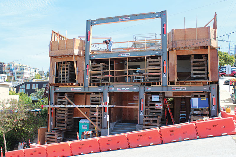
Multi-story multi-bay frame on incline site condition.
Conclusion
Policy makers are trying to address the social and economic risks of the architectural status quo along the West Coast before the next devastating earthquake. A city can strengthen its community by developing a plan and passing ordinances to minimize the effect of inevitable natural events before they occur. Proactively strengthening vulnerable soft-story buildings enhances the resiliency of a city and its communities, and reduces potential loss and damage.
The Simpson Strong-Tie Strong Frame® special moment frame is a solution for strengthening existing buildings and new construction. Several full-scale soft-story tests from the University of California, San Diego, have demonstrated that the Strong Frame SMF can strengthen existing buildings with design flexibility to fine-tune frame performance to match the demands of the building. The bolt-on/bolt-off Yield-Link structural fuse allows for rapid replacement and post-earthquake repair. The no-beam-bracing solution provides another tool for Designers when using steel special moment frames in light-frame structures. High performance, design flexibility, and ease of installation combine to make the Strong Frame special moment frame ideal for meeting the needs of cities and their communities.▪
References
Resilience by Design Report, City of Los Angeles
Association of Bay Area Governments Resilience Program (ABAG) – http://resilience.abag.ca.gov/housing/softstory
Seismic Evaluation and Retrofit of Multi-Unit Wood-Frame Buildings with Weak First Stories (FEMA P-807), May 2012
ANSI/AISC 34110, Seismic Provisions for Structural Steel Buildings
NEES-Soft: Seismic Risk Reduction for Soft-Story Woodframe Buildings (2013)
Gilton, C., Chi, B. and Uang, C.M. (2000), Cyclic Response of RBS Moment Connections: Weak-Axis Configuration and Deep Column Effects, Report No. SSRP-2000/03, Structural Systems Research Project, Department of Structural Engineering, University of California, San Diego, La Jolla, CA.