
Constructed from 1883 to 1898, the Provo Tabernacle was a historical treasure of The Church of Jesus Christ of Latter-day Saints (LDS) and the local community. It seated 1,500 and featured octagonal stair towers, a high-pitched gabled roof, art glass windows, exquisite woodwork, and a central tower topping out at 167 feet above the ground. The building hosted U.S. presidents, musical performances, school commencements, interfaith gatherings, and community events.

Courtesy of Dustin Smith
A four-alarm fire destroyed the building (Figure 1) in December 2010. The exterior was almost all that remained of the Tabernacle. Rather than demolish the structure, the owner enlisted a team of architects, engineers, builders, and historians to assist with an unprecedented reconstruction and restoration project. Reaveley Engineers + Associates (RE+A) was the structural engineering consultant.
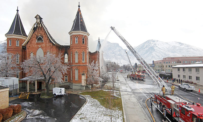
Figure 1. Crews respond to Tabernacle fire.
LDS Church leadership announced the Tabernacle would be rebuilt as a temple. Architecturally prominent, a temple is considered by members of the LDS Church as the most sacred place of worship. The structure serves a much different purpose than a chapel where regular worship services are conducted. This change in use would require the interior spaces be completely reconfigured within the original building envelope to accommodate new building functions.
Challenges & Objectives
A significant challenge faced by the design team was converting a 35,000 square foot historic structure into a modern 85,000 square foot temple without losing historic details. A major excavation would be required to accommodate a basement and sub-basement below the original building, as well as adjacent sub-grade parking, doubling the size of the building. In total, the contractor excavated to 25 feet below grade for approximately 170,000 square feet and 40 feet below grade for approximately 15,000 square feet.
The team had one primary objective: limit settlement or another movement that could cause damage to the existing brick walls. Since the original building had only a crawlspace below the main floor, a system had to be engineered to support and reinforce the existing masonry walls for excavation to take place. The design and construction team explored several excavation and shoring methods that would support the original five-wythe brick masonry walls while excavating two new sub-grade floor levels. A new internal bracing system would also have to be engineered to stabilize the remaining brick walls while the temporary external bracing system that was installed soon after the fire was removed.
The design of the interior bracing system needed to be compact and maximize working space for the contractor. It also had to allow placement of new reinforced shotcrete walls against the interior face of the brick. This bracing system would remain in place until a new structural steel frame was constructed inside the building, and new floor and roof diaphragms were in place to brace the exterior walls.
Selection of the shoring system was influenced by the presence of high groundwater at the site. The sub-basement level and lower part of the basement level would be located below the groundwater elevation. The proposed shoring system would need to ensure placement of the waterproofing membrane below the sub-basement floor and at the exterior face of the foundation walls without compromising the performance of the membrane under significant hydrostatic pressure.
Bracing/Reinforcing the Existing Masonry
Masonry Testing
After the fire, tests were performed on the mortar in the brick walls and revealed minimal damage to the brick and mortar at the interior face of the walls. Most of the damage to the walls was caused by the collapse of the wood roof structure during the fire.
Based on initial observations, it was evident that the mortar consisted of fine aggregate and lime, and was quite weak. Shear strength, compressive strength, and deformation property tests were conducted to assess the mortar’s physical properties. Results indicated the strength of the mortar fell below minimum thresholds. The brick walls did not have sufficient strength to function as shear walls or effectively resist out-of-plane earthquake forces. In short, the brick walls would need to be reinforced and strengthened.
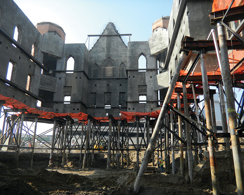
Figure 2. Shotcrete placed on interior face of the brick.
The Solution
The original brick walls are anchored to new reinforced concrete shear walls by placing shotcrete against the interior surface of the brick (Figure 2). Two of the five interior wythes of brick (approximately 8 inches) were removed, and that space was replaced with shotcrete. Essentially, no floor space was lost. The remaining three wythes of brick were permanently anchored to the new shotcrete walls by installing 14-inch to 16-inch-long steel helical anchors into the brick.
In the completed building, the shotcrete walls function as shear walls to resist lateral earthquake and wind loads imposed on the building. The walls also stabilize the existing brick walls against lateral out-of-plane forces.
Approach to the Work
In many areas, the need for thin concrete walls resulted in shear walls and boundary elements that did not comply with prescriptive code requirements. To help the owner gain confidence in the thinner walls performing as desired during an earthquake, the structural engineers completed a performance-based design using non-linear analysis techniques. The results indicated that the thinner shear walls would perform as prescribed to meet code requirements and the owner’s enhanced performance goal of life safety in the Maximum Considered Earthquake.
Because of the reduced thickness, the quantity of reinforcing steel within the walls was greater than normal. Extra care was taken by the contractor to place the shotcrete in the walls while preventing voids behind and between the reinforcing steel. Enhanced inspections were conducted to maintain quality control of the shotcrete placement (Figure 3).
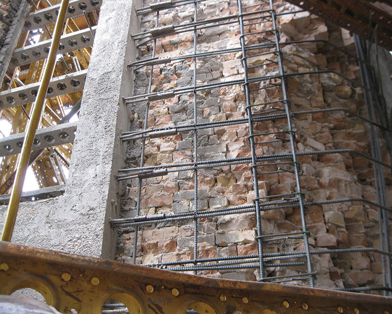
Figure 3. Care was taken with shotcrete placement around reinforcing steel.
Mechanical rebar couplers were placed at the bottom of vertical reinforcing bars within the shotcrete shear walls so that the bars could be extended into the top of the reinforced concrete foundation walls that were placed during a later phase of the project.
After the brick walls had been reinforced and supported by the new concrete walls, steel beams were attached to the concrete walls creating a reinforcing horizontal “ring” near the elevations where new suspended concrete floors would be placed.
Excavation
With the masonry reinforced and strengthened, the next phase was to support the stabilized building shell so excavation could begin. The new composite walls would be supported by cased micro-piles while 30,000 cubic yards of earth were removed.
A series of eight-inch diameter micro-piles were drilled into the ground, on each side of the walls, to a depth of about 90 feet. Some of the piles were battered to resist the temporary lateral loads on the shored walls during construction. Openings were then excavated through the rubble-stone foundation walls just below the brick and shotcrete walls. These openings were aligned between pairs of micro-piles. Steel needle beams were placed through the foundation wall openings and connected to the micro-piles (Figure 4).
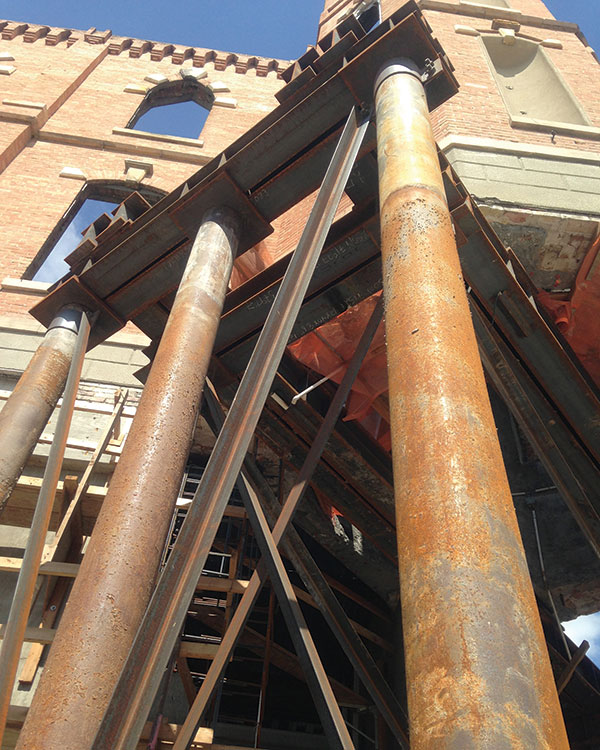
Figure 4. Steel needle beams connected to micro-piles.
Hydraulic jacks were placed between the needle beams and concrete bearing lugs formed into the bottom of the shotcrete walls. The jacks were then loaded to transfer the weight of the walls above onto the needle beams and shoring system. The contractor closely monitored the elevation of the walls during this load transfer to ensure only very slight changes in the elevation.
Once the weight of the walls was transferred into the shoring system, adjustable bearing seats were installed on each side of the jacks and the jacks were removed. Excavation of the surrounding soils then commenced with continued monitoring of the elevation of the structure. As excavation progressed, steel diagonal braces were added between the micro-piles to provide lateral stability and maintain the allowable unbraced length of the micro-piles.
Footings & Foundations
When the bottom of excavation was reached, a waterproofing membrane was installed and a new 18- to 24-inch thick reinforced concrete mat footing was placed. The new sub-basement level is approximately 14 feet below the design groundwater elevation. The mat footing and foundation walls were designed to resist the upward hydrostatic pressures.
The micro-piles served several purposes. First, they temporarily supported the exterior brick walls. Second, they served to support the mat footings for the heavy loads of the new structure. The micro-piles also helped mitigate the potentially liquefiable soils that exist on the site. Lastly, they acted as hold down anchors to resist buoyancy forces created by the water table.
After the new mat footing had been completed, new reinforced concrete foundation walls were constructed between the mat footing and the bottom of the brick walls. Block-outs were formed in the foundation walls around each of the shoring needle beams (Figure 5).
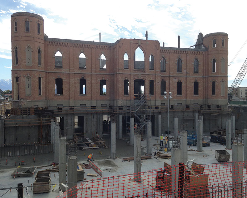
Figure 5. Block-outs in foundation walls.
New Superstructure
With the foundation system complete, the focus shifted to a new structural steel superstructure inside the shell of the existing building. The three new floor structures consist of composite steel beams supported by the new shotcrete exterior walls and interior steel columns.
The reinforcing in the floor slabs was connected to dowels previously set in the shotcrete walls. The dowel system was designed to transfer forces between the walls and the floors, which serve as horizontal diaphragms while providing ductile behavior during an earthquake. The new sloped roof structure consists of a metal roof deck supported by steel beams.
The structure was designed to support the weight and overturning forces imposed by a new center tower matching the pre-1917 original. The restoration of this key architectural feature was of particular import to the owner (Figure 6).
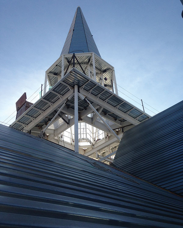
Figure 6. Restoration of center tower.
Parking Garage
To the west and south of the Temple is a new single-level, sub-grade parking garage that connects to an adjacent parking garage. The lid structure over the parking area was designed as a post-tensioned concrete beam and one-way slab system. The typical span of the post-tensioned beams is 60 to 64 feet. Beam spacing varies but is typically about 27 feet-on-center.
This structure supports a beautifully landscaped plaza. The weight of the landscaping overburden (18 to 35 inches of soil), pavements, snow, and plaza live loads combined to create significant loads on the lid structure.
The concrete beams were designed with higher than normal post-tensioning stresses to reduce beam depth as much as practical, while still controlling flexural cracking in the beam section. Careful detailing of the tendon anchorage plates was required to verify that they could fit within the profile of each of the beams. Grade 75 rebar was specified to reduce congestion of the steel reinforcing bars within the beams
Architectural Considerations
Restoring the building to its original state and preserving its historic fabric was a primary architectural objective for principal architect Roger Jackson of FFKR Architects.
Preserving and stabilizing the original brick walls was an initial focus. Also of intense interest was restoring the original central tower. In 1917, the tower was removed because its weight caused excessive deflections in the roof members. The new tower is laterally supported by steel braced frames which transfer forces to the shotcrete shear walls through the roof diaphragm and supplemental bracing. Natural light streaming through windows around the tower illuminate an art glass ceiling in the main upper lobby located directly below the tower.
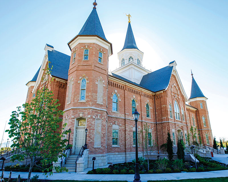
Figure 7. Wood-framed roofs at the four building corners.
Another significant architectural feature of the original Tabernacle was the wood-framed roofs of the octagonal stair towers at the four building corners (Figure 7). One stair was partially burned and damaged by the fire while the other three only suffered minor smoke damage. The tower roofs were each removed as a single piece, and the one damaged tower was rehabilitated and rebuilt to its original configuration. The original straight wood sheathing on the tower roofs was overlaid with new wood structural panel sheathing to stiffen and strengthen the roof structures. Connections between the base of the tower roofs and the walls below were improved to resist the required wind and earthquake loads.
Conclusion
The complex nature of this project demanded unique engineering and construction solutions.
Dynamic, collaborative interactions between owner, architect, structural and geotechnical engineers, contractor and subcontractors generated economic and innovative solutions.
“The contractors and architects have worked in similar situations where they have done underpinning but not at this scale and this height,” said LDS Church project manager Andy Kirby. “The design of this was a process between the architect, our design team, the structural engineers, and the contractors. We came up with multiple options, vetted those out, and then improved it to what you see now.”
Many have called this historic renovation a “once-in-a-lifetime” project. The team understood what this project meant to the owner and community, and championed this vision from beginning to end.▪
Reaveley Engineers + Associates was an Outstanding Award Winner for its Provo City Center Utah LDS Temple project in the 2016 NCSEA Annual Excellence in Structural Engineering Awards Program in the Category – Renovation/Rehabilitation.