
This article provides a better understanding of the design requirements and methods to laterally brace (bridge) axially loaded cold-formed steel stud walls. Cold-formed Steel (CFS) studs provide a cost effective and extremely efficient structural solution for the typical mid-rise building. In recent decades, CFS design has evolved tremendously as the behavior and design constraints of the material continue to be better defined through comprehensive research and testing. As our understanding of the behavior of CFS studs continues to evolve, the height of a typical mid-rise CFS structure continues to increase. Thus, it is more critical to the integrity of the structure that these heavily loaded studs be adequately braced.
Global buckling of an axially loaded stud can occur in one of three modes: flexural buckling, torsional buckling, or flexural-torsional buckling. Bridging is used within the plane of the wall to prevent global buckling and specific performance requirements of the bridging must be maintained.
The bridging methods described herein represent a mechanical bracing design consistent with an “all-steel design” approach. The all-steel design approach indicates that the CFS studs rely on bridging for stability and that bracing by structural sheathing or gypsum wallboard is not typically considered for axial load stability in the design. One primary reason that CFS walls in mid-rise buildings require an all-steel design bridging approach is that the lower floors may go unsheathed for weeks at a time during construction. Also, for axially loaded walls, it is an industry practice to disregard gypsum sheathing as a structural brace because of durability issues associated with possible water damage. It should be noted that bridging requirements for studs loaded laterally, perpendicular to the plane of the wall, are not discussed herein. Brace forces for studs with combined axial and lateral loading are additive, and the designer is encouraged to refer to The American Iron and Steel Institute (AISI) design guide, Cold-Formed Steel Framing Design Guide (AISI D110-16) where a design example showing the interaction check for combined loading condition can be found.
Design Requirements
The design requirements for the bridging components of axially loaded cold-formed steel studs are described in the North American Specification for the Design of Cold-Formed Steel Structural Members, AISI S100-12, Section D3.3, and Section B3.1 of the North American Standard for Cold-Formed Steel Framing – Wall Stud Design, AISI S211-12.
AISI S100 Section D.3.3, Bracing of Axially Loaded Compression Members, gives both a strength and stiffness design approach. The required strength of the brace to restrain lateral translation at a brace point for an individual compression member is given as:
Prb = 0.01Pra (Eq. D3.3-1)
The required brace stiffness for the ASD design method is given as:
βrb = [pmath]{2[4-(2/n)]}/L_b[/pmath] (ΩPra), Ω = 2.0 (Eq. D3.3-2a)
While the required brace stiffness for LRFD and LSD design methods is given as:
βrb = [pmath]{2[4-(2/n)]}/L_b[/pmath] ([pmath]P_ra/phi[/pmath]), φ = 0.75 (LRFD) or 0.70 (LSD) (Eq. D3.3-2b)
where,
Prb = Required brace strength (brace force) to brace a single compression member with an axial load Pra
Pra = Required compressive axial strength [compressive axial force] of individual concentrically loaded compression member to be braced
βrb = Minimum required brace stiffness to brace a single compression member
n = Number of equally spaced intermediate brace locations
Lb = Distance between braces on individual concentrically loaded compression member to be braced,
AISI S211 Section B3.1, Intermediate Brace Design, states that: “For axially loaded members, each intermediate brace shall be designed for 2% of the design compression force in the member.”
When using AISI S211 approach, there is no explicit brace stiffness requirement compared to the approach in AISI S100. As a result, AISI S211 uses a more conservative strength requirement, 2%, compared to 1% in equation D3.3-1 in AISI S100.
Bridging Methods
Several bracing concepts are available to effectively brace axially loaded CFS against both flexural and torsional buckling modes. The methods of bracing may be categorized into three groups: tension systems, tension-compression systems, and compression systems. Regardless of the type of bracing used, the bridging must be effectively continuous between anchorage points. Where bridging is spliced, engineered splice details are required to maintain the performance requirements of the bridging along the length of the entire wall.
Tension System
In a tension system (Figure 1), the bridging member is designed to resist the stud buckling by means of pure tension. An example of a pure tension system consists of flat straps attached to both flanges of the stud with blocking at intervals along the wall to provide resistance to the rotation tendency of the studs within the wall. This type of bridging is advantageous in scenarios requiring a significant number of mechanical and electrical utilities within the wall plane. However, installation requires access to both sides of the wall, and the flat straps must be installed tight enough to provide the required stiffness. The flat straps are typically attached to each stud flange with screws. The blocking is set at the required intervals (typically first and last stud spaces and at 8 to 12 feet on center) to resist the rotation and is attached to the flat straps on each side of the wall as shown in Figure 1.
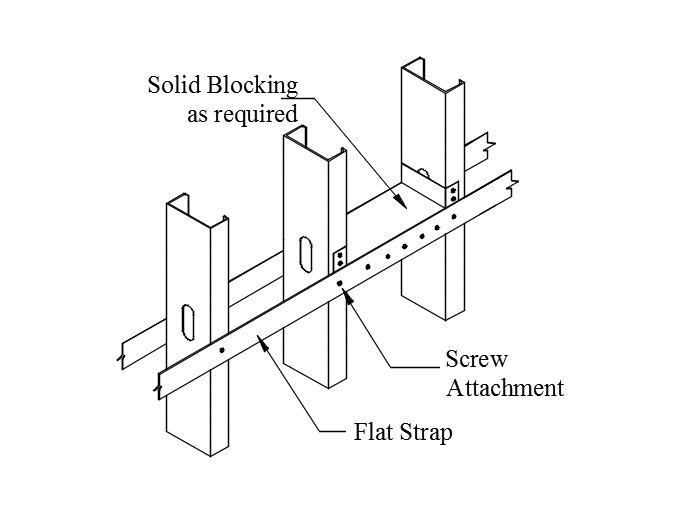
Figure 1. Flat strap “tension” bridging system.
Tension-Compression Systems
A bridging system having the capability to resist the buckling of the stud in either tension or compression is illustrated in Figure 2. An example of this type of system is a cold-rolled channel inserted through the punch-outs of the studs with a clip attaching the bridging member to each stud. The clip transfers the load induced from the flexural and torsional buckling of the stud into the bridging line. A static analysis suggests that the cold-rolled channel functions in 50% compression and 50% tension between “anchorage” points. This concept is illustrated in a design example given in CFSEI Tech Note W400-16. The typical cold-rolled channel member used for a load bearing stud wall application is a 150U50-54, 33 ksi section. The advantage of this bridging method is that it requires access to only one side of the stud wall for installation. The disadvantage is that the stud punch-outs must align horizontally for the channel to be inserted continuously throughout the wall length.
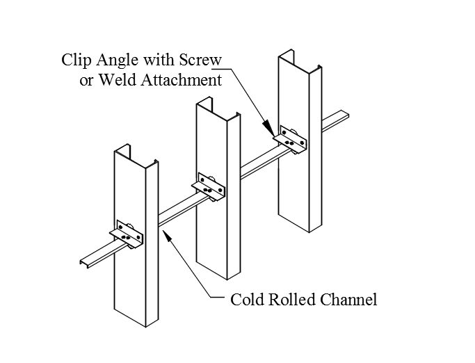
Figure 2. Cold-rolled channel “tension-compression” bridging system.
Compression-Only System
A compression-only system is capable of resisting stud flexural and torsional buckling using compression only (Figure 3). The compression system may offer higher brace stiffness compared to the tension and the tension-compression bridging systems.
Load and stiffness capacities of the three bracing concepts can be achieved through engineering calculations. Proprietary bridging members offer the advantage that they have also been tested.
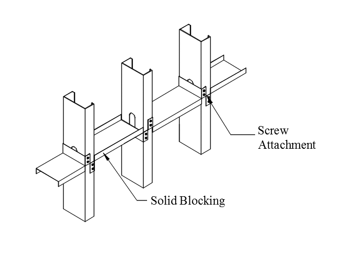
Figure 3. Continuous blocking “compression” bridging system.
Refer to Cold-Formed Steel Engineers Institute TN W400-16, www.cfsei.org, for a numerical example problem illustrating the design of a bridging member. The design example provides the detailed calculations for bracing (bridging) and bridging anchorage of axially loaded studs, and compares the AISI S100 and AISI S211 bracing design alternatives that are available to designers.
In Summation
To ensure the integrity of the structure, the design engineer must fully understand the behavior and bracing requirements of a CFS load bearing stud. An integral part of the bracing requirements is the bridging required in the wall to prevent the tendency of a cold-formed steel stud to buckle about its weak axis under increasing load. For the bridging to be effective, it must be anchored periodically as the accumulation of the bridging force approaches the allowable capacity of the bridging method used. The contents of this article have offered an overview of the current code requirements for the design of the common framing methods of achieving the bracing requirements. The reader is encouraged to refer to the standards referenced above for additional information.▪