
The 783,800-square-foot Zurich North America Headquarters is the largest build-to-suit office project completed in the Chicago area in the last 15 years, but this striking addition to the I-90 corridor in Schaumburg is not just notable for its size. The unique building form is comprised of the three long rectangular bars shown in Figure 1. The east and west lower bars rise six stories from the ground, while the five-story upper bar sits on top of – and spans between – the two lower bars.
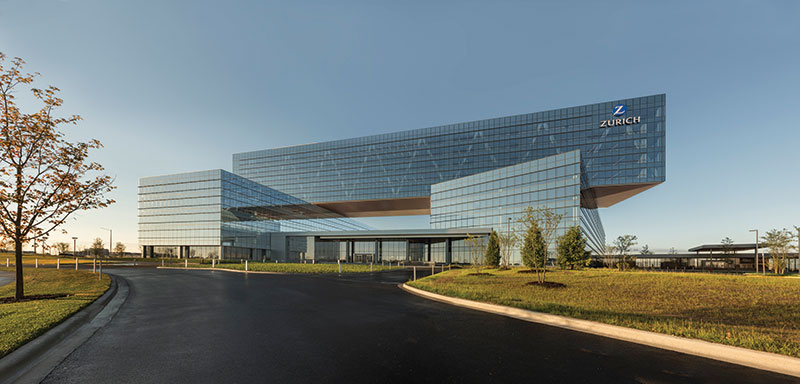
Courtesy of James Steinkamp Photography.
A Building and a Bridge
The dramatic 180-foot main span and the two 60-foot cantilever spans on each end are made possible by two steel trusses at the exterior faces of the upper bar and a third truss centrally located in the interior. Usually, a requirement to transfer five levels of office loading over such long spans would be an arduous task associated with a significant cost premium. In this case, however, loads from the upper bar are not carried by a one-story or two-story transfer truss. Instead, the main structure of the entire upper bar is a truss. By replacing vertical columns with truss diagonals throughout the entire five-story upper bar office space, the full 68-foot height of the space becomes structural depth for the truss, allowing chord axial forces to be minimized.
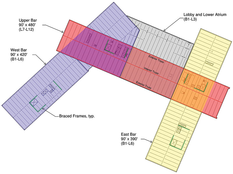
Figure 1. Plan diagram.
Additional efficiency is achieved by making the truss continuous over its supports, and ideally proportioning the cantilever spans to balance forces and deflections in the main span. These effects further reduce chord axial forces and result in deflections which are approximately equal at the main span and the cantilevers.
Although the depth and continuity of the trusses make them inherently stiff, and therefore not prone to large deflections, the trusses were fabricated and erected with slight cambers to mitigate concerns about floor levelness. By super-elevating initial panel point elevations by up to one inch, the initial truss deflection due to dead load was effectively eliminated. Meanwhile, live load deflections are less than ¾-inch at both the main span and the cantilevers.
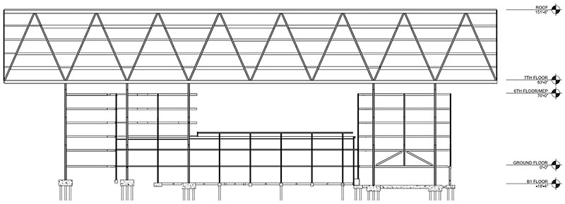
Figure 2. Typical main truss elevation.
Truss Design
The design of the truss chords was governed by the axial truss forces acting in combination with significant bending moments, since the chords also act as 60-foot continuous W36 steel girders supporting the conventional 45-foot composite steel framing. A series of large truss chord penetrations (40 inches wide x 22 inches high) were carefully coordinated to allow mechanical services to fit within the standard 13-foot-six-inch floor-to-floor heights without compromising the ceiling height.
While coordination of the deep truss chords with mechanical services was a challenge, coordination of the truss diagonals with the interior office space was less so. As the centerpiece to the most iconic component of the project, the trusses are featured and celebrated by the architecture rather than hidden behind partition walls.
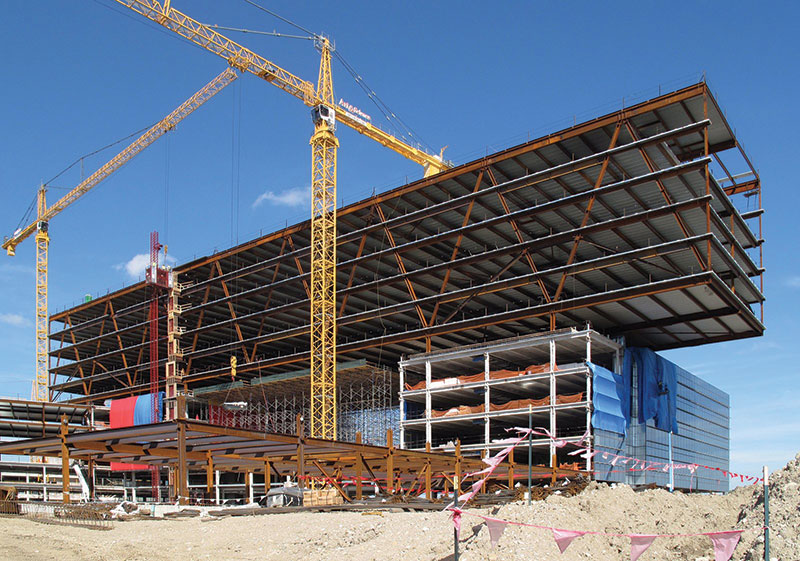
Figure 3. Construction of five-story upper bar. Courtesy of Goettsch Partners.
Early in the design phase, the design team worked closely with the contractor’s connection engineer to develop economical splices and compact connections at the truss nodes. The typical truss diagonal-to-chord node (Figure 4) was shop-welded and delivered to the site in one piece with the chord, with bolted diagonal splices accommodated on both sides of the node. Where possible, bolt quantities were reduced by taking advantage of bearing, such as in compression diagonals which were not subject to load reversals.
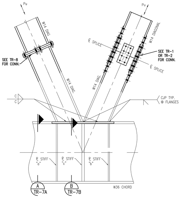
Figure 4. Typical truss diagonal-to-chord node. The force in the compression diagonal (left) is transferred primarily through bearing. Courtesy of Ruby Associates.
Braced Frames
With a roof height of 152 feet, the building will not be confused with the tallest high-rise office buildings found in downtown Chicago. Still, the 480-foot wide wind sail of the upper bar, in combination with the Exposure C wind loads blowing off the expressway from the south, creates substantial overturning forces that required creativity in the layout of the two braced frame cores which stabilize each end of the upper bar.
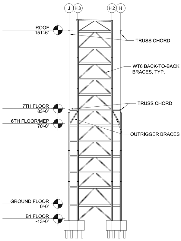
Figure 5. Typical elevation of primary north-south-braced frames.
The typical elevation of the primary north-south braced frames is shown in Figure 5. It was critical to take advantage of the large gravity loads present in the columns supporting the main trusses to minimize foundation tensions. However, the trusses are laid out on a 45-foot module, while the extent of the braced frames was limited to the 29-foot-8-inch width of the elevator core. Outrigger braces were provided directly beneath the upper bar at the Level 6 mechanical level at each of the four brace lines to engage the truss support columns and their beneficial gravity loads. In addition to reducing the uplift forces, the extra depth of the structural system, combined with the high axial stiffness of the large truss support columns, ensured that lateral drifts could be controlled with a minimal steel weight premium beyond what was required for strength.
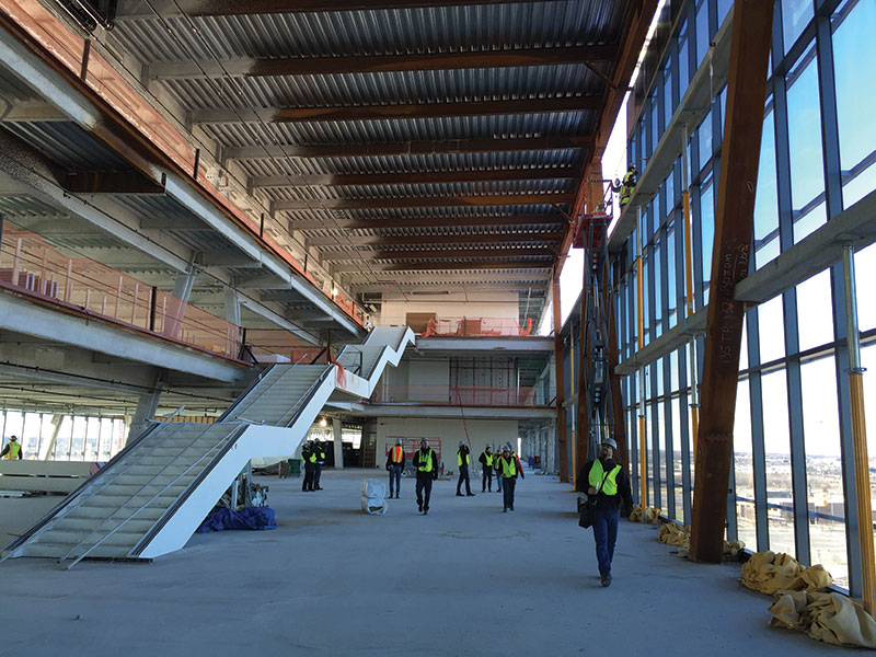
Figure 6. Upper bar atrium with long-span steel staircase connecting levels 9, 10, and 11. Courtesy of Goettsch Partners.
Open Spaces
Four large atrium spaces give the interior a dramatic feel befitting the project, and a series of feature staircases connect the various levels served by the atriums. The longest, shown in Figure 6, spans 40 feet between Level 9 and a 17-foot cantilever landing at Level 10, and another 50 feet between the Level 10 landing and Level 11.
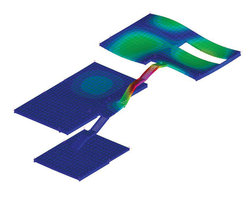
Figure 7. Atrium staircase primary mode of vibration.
Given the susceptibility of long-span staircases to vibration, a series of dynamic analyses were undertaken to predict the vertical accelerations at mid-span of the stair under the worst case of a rapidly descending individual. Since the dynamic response of a long-span stair is a highly nonlinear problem, it is possible for a moderate increase in stiffness to result in dramatically improved behavior. In this case, the initial stair design based on strength and deflection was stiffened by optimizing the steel stringer profile, with a 3-inch increase in depth and a modest increase in steel weight. This reduced the estimated stair accelerations under the controlling case by more than a factor of 3 (Figure 8) compared to the initial design.
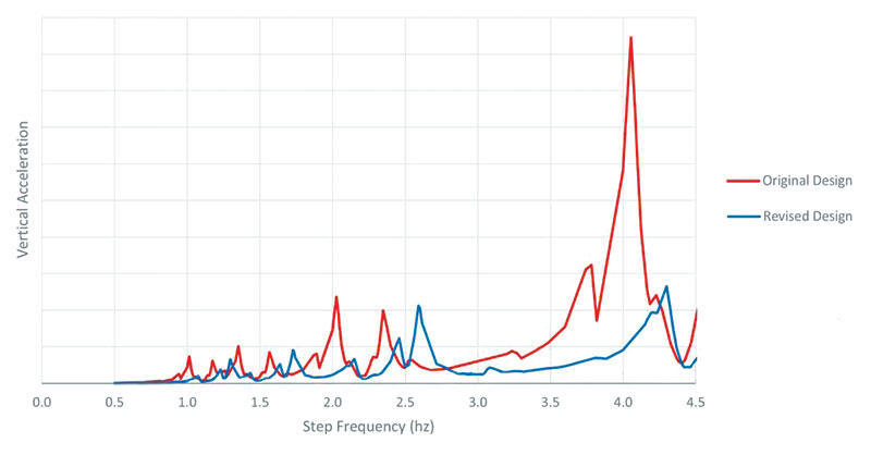
Figure 8. Vertical acceleration at mid-span of staircase versus step frequency of a descending individual.
Challenging Soil Conditions
Ground conditions at the site consisted of significant regions of soft fill and organic clays, particularly on the south end of the site where, as shown in Figure 10, a large pond had previously existed. To mitigate differential settlements during and after construction, an innovative “preloading” program was undertaken in which approximately 20 feet of soil from the adjacent parking garage excavation was piled on top of the entire building area of the site. Over the course of 60 days, the weight of the additional fill, in conjunction with 20 to 35-foot long vertical “wick drains” arranged in a 5-foot triangular grid pattern, accelerated the consolidation and settlement of the soft organic material. Upwards of three feet of settlement was observed during the preloading phase; additional settlement after construction is anticipated to be limited to approximately one inch.
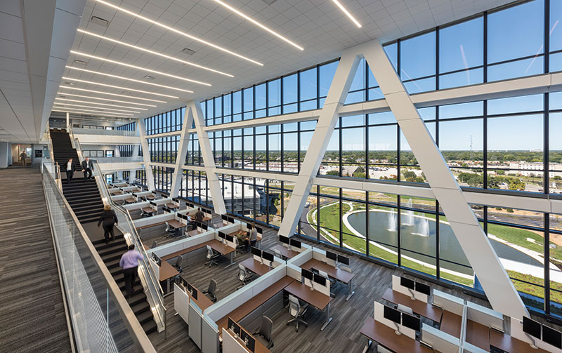
Figure 9. View from level 10 of the upper bar atrium. Courtesy of James Steinkamp Photography.
Had the preloading program not been implemented, a significant portion of the settlement would have occurred after construction. Also, a suspended slab system would have been required in the basement rather than the traditional slab-on-grade which was ultimately used. Moreover, the continuous flight auger (CFA) piles used for the deep foundation system would have been subjected to “down-drag” forces – essentially negative skin friction – as the surrounding soils consolidated. The resulting reduced capacities would have required significantly more piles and associated expense.
Notably, the preloading and drainage program also mitigated the susceptibility of the soils to liquefaction under seismic loads, allowing the seismic site classification to be reduced from F to D. This corresponds to a considerable reduction in seismic forces and detailing requirements, and eliminated the need to perform a site-specific seismic response analysis.
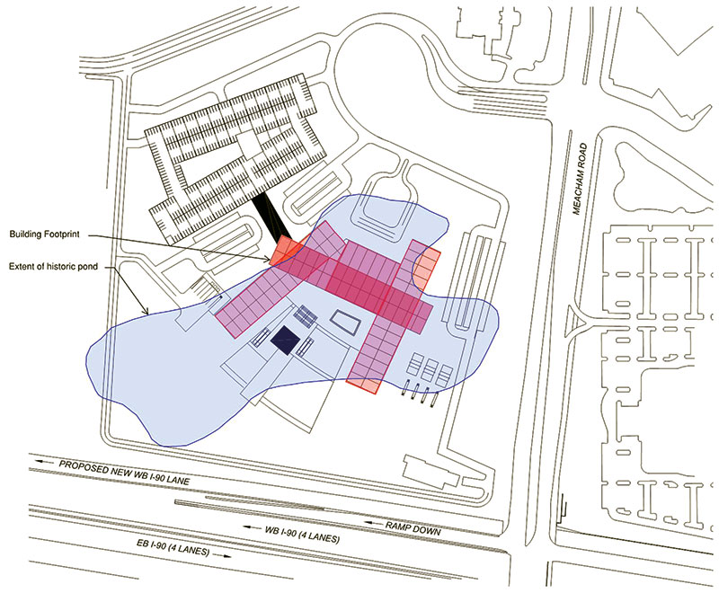
Figure 10. The extent of the old pond encompasses the majority of the building footprint.
Conclusion
A careful integration of structure – in particular, the three structural steel trusses of the suspended upper bar – allowed this iconic piece of architecture to stand apart from its peers in the suburban office building landscape. After opening in October 2016 to rave reviews from occupants and critics alike, it is clear that the Zurich North America Headquarters has quite literally raised the bar for the suburban office building.▪
Project Team
Owner: SFG Schaumburg 1, LLC
Structural Engineer: Halvorson and Partners, a WSP | Parsons Brinckerhoff Company
Occupant: Zurich North America
Developer/Design-Builder: Clayco
Architect: Goettsch Partners
Geotechnical Engineer: GEI Consultants