
In Ground Improvement for Building Support by Damian R. Siebert, P.E. and Steven R. Kraemer, P.E. (STRUCTURE, July 2015), we learn more about issues surrounding the ground improvement (GI) for a building support system (stone columns, aggregate piers placed under reinforced concrete footing). It is an intermediate foundation system, i.e. the system between shallow spread footings and deep pile foundation systems. Although the system has been around in Europe since the 1930s and in the U.S. about a decade later, it remains mostly in the hands of the specialty contractor’s foundation engineers.
Siebert and Kraemer state the following in their article:
As applications of GI are being pushed to new limits, the need for deep understanding of installation conditions, behavior, and adequate quality assurance becomes more critical. The adequacy of GI in bearing capacity applications cannot be assumed simply because of its successful legacy for settlement control. In such challenging applications, the Engineer(s)-of-Record (EOR) and project team must ensure that the GI provides comparable bearing capacity, settlement control, resiliency during earthquake and other loading conditions, quality assurance and overall performance as other “conventional” foundation systems. Experience is proving that this is easier said than done.
In practice, the GI specialty contractor engineer provides the Structural Engineer of Record (SER) with the equivalent uniform bearing capacity to size the footings for the building foundation walls and columns. When asked the overall Factor of Safety of the system, the answer cannot be obtained consistently. Instead, the GI specialty contractor engineer stresses that, for design adequacy, it is critical to know the traditional maximum acceptable settlement and the maximum differential settlement between columns. The SER’s only foundation design involvement for most projects is to review and approve the GI foundation system shop drawings (size of footings and locations of the piers, general construction/installation notes, and specifications, etc.) prior to installation.
The design concept of the GI foundation system for building support is to combine the bearing capacity of all piers and compressed soil under the footing and convert this total bearing capacity into the equivalent uniform bearing capacity for conventional spread footing design. Figure 1 shows typical single-, 2-, 3-, and 4-pier footing layouts under the square or rectangular concrete footing. The number of piers used under the footing can be as many as practically needed.

Figure 1.
On a typical project, the GI foundation engineer evaluates the type of soil, determines the proposed improvement (diameter and length/depth of the aggregate piers), and calculates the stress modulus (stress per unit settlement) of the pier and the soil surrounding the pier. Kp is the stress modulus of the Pier and Ks is for the soil. The ratio Rs = Kp / Ks is obtained for use in determining the equivalent bearing capacity. The Rs values between 8 and 14 are normally used in practice, although a value as high as 40 is possible.

Figure 2.
Having reviewed these GI foundation system shop drawings in the past, and more recently as a structural engineer or plan reviewer, the authors found that the geometrical layout of the 3-pier footing shown on some of the contractor’s shop drawings has substantial eccentricity. The footing, therefore, might not be adequate for the design intent (Figure 2a). Figure 2b shows a correct layout of the piers in the 3-pier footing. The three piers should be installed in an equilateral triangle to each other, and the centroid of the piers and the soil under the footing coincide with the centerline of the footing (column center lines). For convenience in determining the centroid of the AP/soil matrix (3 piers and the soil surrounding the piers under the footing), one can write:
Total capacity, P = (Rs-1) (3) (Ap) qs + (a) (b) qs
Where Ap is the area of the aggregate pier, qs is the soil pressure under the footing, and a and b are the footing dimensions. The centroid of the above two terms, as well as the total force, can be easily found.
Another concern that deserves the attention of the SER and the GI foundation engineer is the eccentricity of the single- and 2-pier footings. No matter how skilled the installer is, there will have to be some eccentricity when installing the piers. The single- and 2-pier footings are very sensitive to the eccentricity loading, and their capacity is substantially reduced when subjected to even a small eccentricity.
Example
Determine the capacity of a single-pier footing having the centerline of the aggregate pier installed 6 inches away from the building column centerline (6 inches is the acceptable construction tolerance). The footing is 4 feet x 4 feet (12 inches thick), and the aggregate pier diameter is 30 inches (Figure 3). The stress ratio (Rs = 10, the given equivalent allowable bearing capacity) is 6,000 pounds per square foot.
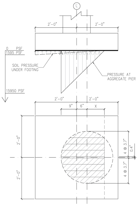
Figure 3.
Solution: If the aggregate pier were installed right at the center of the column, the capacity would be (4 x 4) x 6,000 = 96,000 pounds. With the stress ratio, Rs =10, and bearing stress, qs as the stress of the soil under the footing, we have
(4 x 4) qs + (10 – 1) π (15/12)2 qs = 96,000
qs = 1,595 psf
Since the eccentricity is outside the “kern” (the area at the center of the pier having a radius of ¼ of the pier radius, i.e. 15 ÷ 4 = 3.75 inches), we know that the footing is not likely to be fully effective. Therefore, let’s assume the footing has zero stress near the edge of the pier (see the stress distribution on Figure 3). To find the total resultant force under the footing, we subdivide the circular area of the pier into nine (9) strip areas as shown, and with the stress distribution associated with each area, the forces at each strip and under the remaining area is a function of “X”. By taking moments about the line of zero stress, we find the distance X equals 16.80 inches, and the total force equals 51,140 pounds. We can conclude that the capacity is reduced from the ideal of 96,000 pounds to 51,140 pounds, or reduced to 53.3 % of the ideal.
Estimate of the Capacity
The contact pressure between the footing and the pier is similar to the contact pressure between a circular footing and the soil underneath. Therefore, we can utilize the empirical formula from previously published resources. Considering contact pressures under the footing independently, we find from the example:
Total capacity, P ≈ (Rs–1) qs x Ap/k + (4 x 4) qs
= (10 – 1) x 1595 x 4.909 / 2.70 + 16 x 1595
= 26,100 + 25,520 = 51,620 lbs.
Where k is the value from the Table. In this instance, the estimate (51,620 pounds) happens to be, coincidentally, a very close approximation of the example solution. The more accurate and reliable value should always come from computation as illustrated in the design example.

Table of values (k) for determining pressure (q) under circular footing.*
Conclusion
When designing the aggregate pier single- and 2-pier footings, one must take into account the field-installed eccentricity loading on the pier(s). As demonstrated in the example, the capacity is greatly reduced even when installed within the construction tolerance. The GI foundation engineer and the SER must be aware of this reduced capacity and adjust the design accordingly. The eccentricity for the 3-pier footing addressed in this article is from a contractor’s incorrect layout of the piers (Figure 2a) and can easily be fixed.
Final Note
The eccentricity issues of the pier(s) footings addressed in this article can certainly be detected and resolved during the design process or shop drawings review by the SER. Also, other technical and non-technical issues, as described by Siebert and Kraemer in their article, should be addressed as soon as possible. Perhaps a task force consisting of academics, representatives from the ground improvement foundation industry, geotechnical and structural engineering groups, and the model codes developing organizations such as the International Code Council (ICC) is needed.▪
References
1) Das, B.M. (2007), Principles of Foundation Engineering, 7th Edition, Nelson / Thomson Canada Limited, Canada.
2) Den Hartog, J. P. (1949), Strength of Materials, McGraw-Hill Book Company Inc., New York, NY.
3) Lawton, E.C., and Warner, B.J. (2004), Performance of a group of Geopier elements loaded in compression compared to single Geopier elements and unreinforced soil, Final Report, University of Utah, Salt Lake City, UT.
4) Seckinger, A.H. (2005), Soil Pressure under Footings, STRUCTURE, June 2005, NCSEA, Chicago, IL.
5) Teng, W.C. (1962), Foundation Design, Prentice-Hall International, Inc., Englewood Cliffs, NJ.