
A New FRP Solution for Strengthening Concrete Telecommunication Towers
The wireless communications industry has experienced exponential growth in recent years. Not only is the number of customers increasing, but the amount of information being transmitted through these networks is also increasing. Whereas a decade ago we used our mobile phones strictly for voice transmission, the introduction of the smartphone has increased the demand on the networks and the supporting infrastructure.
In response to this growth, and as we migrate from 3G to 4G and beyond, wireless companies, such as AT&T, Sprint, and Verizon, must provide additional equipment on the towers they lease. These wireless companies lease towers from businesses like Crown Castle, American Tower, or others. Each entity owns and maintains approximately 40,000 towers in the U.S. Occasionally, installing additional equipment on existing towers results in overstressed structures. Towers or poles that were originally installed some twenty years ago are often located in congested areas where obtaining permits for installation of new towers is very difficult and time-consuming.
Prestressed concrete poles are typically designed for a single carrier based on the code requirements at the time of design. Future antenna additions or code changes may lead to the structure not having sufficient capacity. Options for reinforcing theses structure are limited and may not be cost effective.
A typical structural upgrade to steel monopole towers is to bolt flat plate steel sections onto the pole for additional reinforcement. This solution is not feasible on a concrete pole, as there is no economical way to attach the steel to the pole through bolting or welding. Another option is to use guy wires. However, this is impractical since it requires additional land and ongoing maintenance and inspection. A third option is to add a steel lattice structure to wrap around the existing tower, which may not be economical as it leads to building a new structure and foundation. Moreover, obtaining permits and meeting local zoning requirements may prohibit such repairs. A fourth option involves the use of Fiber Reinforced Polymer (FRP) as described in the case study below.
In parallel with this need for strengthening, there is a growing interest in the western United States to upgrade these towers seismically. It is obvious that, in the hours immediately following a large earthquake, wireless communication is in high demand and the system must be designed to survive such an event. For example, Los Angeles recently introduced an ordinance requiring all telecommunication towers to be upgraded to survive the impending “big” earthquake.
Case Study
This case study presents the first known application of an innovative FRP solution to strengthening a structurally deficient tapered prestressed concrete telecommunication tower. The successful completion of this project has led to the identification for retrofit in the immediate future of approximately fifty similar concrete poles.
The structure is a 75-foot long hollow precast concrete pole located in Tehachapi, California (Figure 6). The bottom 15 feet of the pole is directly embedded in the soil, leaving the remaining 60 feet above ground. The outside diameter of the pole ranges from 31.59 inches at 15 feet elevation to 15.39 inches at 60 feet elevation. The thickness of the tube tapers from 3.4 to 2.5 inches, respectively. Reinforcing steel is comprised of twelve ½-inch diameter 270k seven-wire strands uniformly placed around the circumference. The design compressive strength of concrete was 9500 psi.
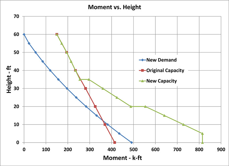
Figure 1. Demand and capacity of the pole at various elevations.
The pole was analyzed for all dead and live load effects, including lateral loads from wind and earthquake. The controlling design moments are shown in Figure 1. The original capacity of the pole at the base was about 420 kip-ft. The capacity had to be increased by nearly 50% at the base to safely resist currently anticipated loads. Detailed analysis of the structure demonstrated both compressive and tensile stresses in the pole exceeded the allowable limits under the new loads. The new design also provides enough reserve capacity to accommodate future additional demands on the tower.
The FRP Alternative
Fiber Reinforced Polymer (FRP) products have high tensile strength and can easily address the shortcomings of the pole. However, the compressive strength of FRP is lower than its tensile strength. In most retrofit projects, it is not uncommon to ignore the compressive strength of the FRP. This meant that conventional concrete or grout had to be added to the pole to increase the pole thickness and thereby reduce the compressive stresses below the allowable limits.
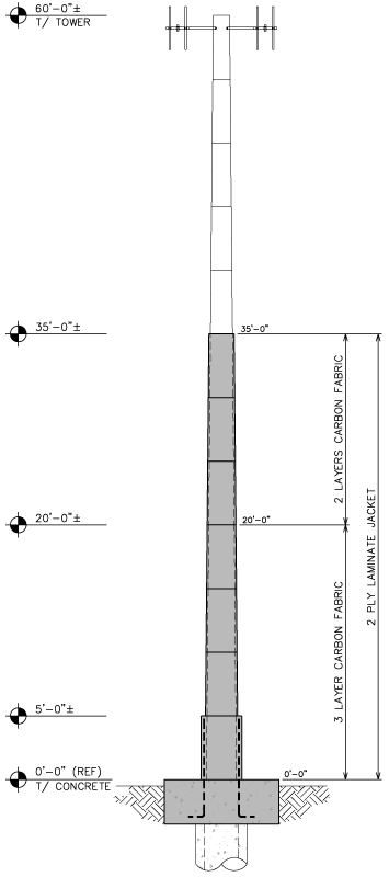
Figure 2. Elevation of the pole for the retrofit scheme using FRP.
Among the options considered, the use of FRP offered the most viable solution (Figure 2). The repair technique offered the flexibility to easily change the strength of the pole along the height. Tension reinforcement for the pole was provided by bonding unidirectional carbon fabrics to the exterior surface of the pole. The carbon fabric used for this project was supplied in 24-inch-wide rolls and had a tensile strength of over 6 kips per inch of width of the fabric. The fabric can be cut into narrower bands for ease of installation without any adverse effect on its strength.
Based on the analysis, 3 layers of carbon fabric saturated with epoxy were required on the lower 20 feet of the pole. Only 2 layers were required between 20 and 35 feet. Elevations above 35 feet required no strengthening. The sudden change in capacity of the retrofitted pole at these elevations, shown in Figure 1, is due to the change in the number of layers of carbon fabric. For confinement, and to eliminate any interference with the antennae signals, 2-foot wide bands of a unidirectional glass fabric saturated with epoxy were wrapped in the hoop direction over all of the carbon fabric for elevations 0 to 35 feet (Figure 3).
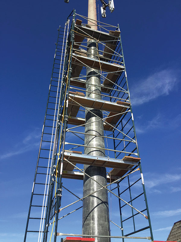
Figure 3. Carbon and glass FRP fabric applied to the lower 35 feet of the pole.
The additional tensile reinforcement resulted in the concrete in the walls of the pole to exceed acceptable compression limits. Therefore, the pole wall thickness had to be increased by 1.5 inches between elevations of 5 to 35 feet to achieve the allowable compressive stresses. Placing a 1.5-inch thick concrete over the tapering pole presented a challenging construction issue. Use of prefabricated steel or wood formwork would have added significant cost to the project.
A special FRP laminate was developed during two decades of R&D that offered an economical solution for this problem. PileMedic® laminates are made by saturating rolls of fabric with resin and running them through a special press that applies heat and pressure, resulting in 4-foot wide rolls with a thickness as little as 0.01 inch. The relatively large width and small thickness of the laminates make their manufacturing unique and challenging. The thin laminates can be easily cut (Figure 4) and wrapped around a column of any shape or size, in the field, to create a stay-in-place form that can be filled with grout or resin.
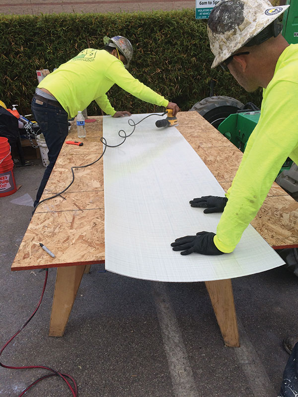
Figure 4. PileMedic laminates being cut to size on the job site before it is wrapped around the pole.
The properties of these laminates are listed in the Table. Depending on their composition, the laminates offer exceptional tensile strength in the longitudinal direction, or in the longitudinal and transverse directions. For this project, the biaxial glass laminate with a thickness of 0.026 inches was used. For the region between 5 and 35 feet, the 4-foot wide laminates were coated with an epoxy paste and wrapped around the pole to create a two-ply shell. Temporary 1½-inch thick spacers, such as a PVC pipe, can be attached to the pole surface to facilitate the wrapping of the laminates with the necessary standoff distance. By overlapping the 4-foot wide laminates by 4 inches, a long shell was created, in the field, that covered the pole at the necessary elevation.

Table of material properties of FRP laminate.
A structural shell created in this fashion provides the equivalent of No. 4 Gr. 40 ties at a spacing of 2½-inches on-center. The shell also provides tensile reinforcement equivalent to No. 4 Gr. 40 steel reinforcing bars distributed at 2½-inches on-center around the pole. For this project, these contributions were ignored. The selection of glass over carbon laminates was based on the electrical insulating properties of the former. At this stage, the shell is not bonded to the pole. An expansive non-shrink grout with a compressive strength of 6000 psi was used to fill the 1.5-inch thick annular space between the jacket and the pole.
At the base of the pole, a new 9-foot x15-foot x1.5-foot concrete mat foundation was installed. The rectangular shape was required to fit within the tight footprint of the tower compound. The new foundation reinforces the existing direct embed pole through load sharing. The forces were proportioned to each foundation element based on the relative member stiffness and soil stiffness. The concrete mat also terminates the FRP. Fifteen No. 8 hooked dowels, extended four feet above grade, transfer the forces from the FRP into the mat foundation. These bars were placed to accommodate the access port for cables entering the core of the tower (Figure 5). The FRP fabric in that region was coated with a layer of sand for improved bond and transfer of stresses. A shell with an outside diameter of 38.5 inches was created at the lower 5 feet, corresponding to a 5-inch thick annular space. As can be seen in Figure 1, this resulted in a very conservative design near the base of the pole.
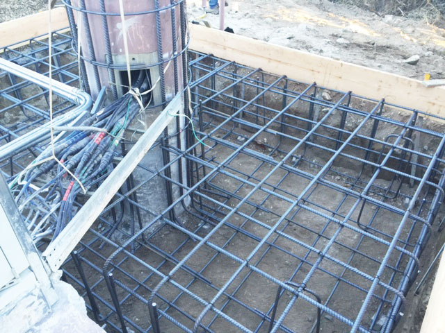
Figure 5. Foundation and the steel dowels at the base of the pole.
Field Installation
The strengthening solution presented herein takes approximately 4 days to install. The lightweight laminates eliminate the need for any heavy equipment and all work can be accomplished using scaffolding (Figure 6). The finished laminates are coated with a UV-resistant coating. Many cables and appurtenances that were near or attached to the pole were moved slightly to accommodate the FRP and concrete placement. These were eventually relocated back to their original positions (Figures 5 and 6). This design approach allows the pole to remain fully operational during the repair, with little change in the appearance and size of the pole.
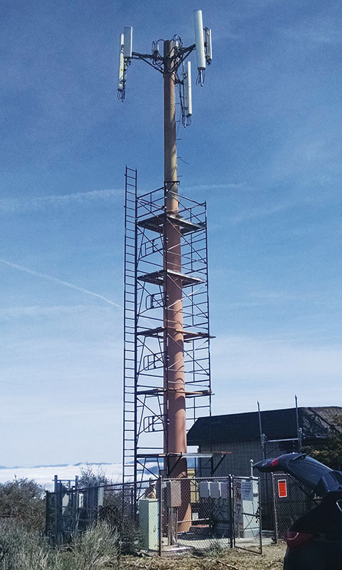
Figure 6. Painted pole at the conclusion of the project.
Over thirty monopoles were reinforced in the greater Los Angeles basin in 2015. Many more such repairs have been identified for completion in 2016 and beyond. The FRP design provides an economical solution to reinforcing concrete poles not available just a short time ago. The FRP solution is a vital part in accommodating the increasing demands of the rapidly growing wireless communication industry. A video showing the field installation of such monopole towers is available online and can be viewed at http://goo.gl/L7pxJb▪
Acknowledgements
The products and the strengthening technique described in this article are protected by U.S. Patent Nos. 8,650,831 and 9,376,782 and several other U.S. and international pending patent applications. The tower and foundation design was performed by Tower Engineering Professionals, Raleigh, NC, in conjunction with QuakeWrap Inc., Tucson, AZ. Field installation of this project was conducted by FRP Construction, LLC, Tucson, AZ.