
This article provides an overview of a bolt design example utilizing the American Wood Council’s (AWC) 2015 National Design Specification® (NDS®) for Wood Construction. Topics include connection design philosophies and behavior, an overview of 2015 NDS provisions related to bolt design including local stresses in fastener groups, and a detailed design example.
Connection Design Philosophies
Discussion of several important design philosophies should help designers better understand connection design for wood members. First, wood is anisotropic, meaning it has different strength properties in various directions: longitudinal, tangential, and radial. Wood is composed of elongated, round, or rectangular tube-like cells. A simple analogy is to imagine the cellular nature of wood as a bundle of drinking straws. When axial compression is applied, the “bundle” is strong longitudinally and connecting the ends, primarily for bearing, is very simple. The “bundle” can also develop considerable tensile strength. Therefore, aligning connections so that loads are transferred concentrically along the length of the wood member is the most efficient design philosophy. However, this is not always practical or possible.
Continuing the analogy, if the load is applied perpendicular to the longitudinal axis of the “bundle” in compression, the straws tend to crush because of the weaker cell walls relative to the axial direction. While capacities are more limited when wood is loaded in compression perpendicular to grain (versus parallel to grain), the limits for bearing conditions on the surface of wood members are deformation-based, not strength-based, and published design values can be increased for smaller bearing areas. Accordingly, dowel bearing strengths are higher relative to compression parallel or compression perpendicular to grain design values. However, dowel bearing strengths perpendicular to grain are lower relative to dowel bearing strengths parallel to grain for larger diameter (>¼ inch) fasteners (see Table).

Design values from 2015 NDS and 2015 NDS Supplement (psi).
When tension is applied perpendicular to grain, the “bundles” tend to separate. Low strength values for this property can be encountered in commercial grades of lumber. For this reason, no sawn lumber tension design values perpendicular to grain have been published in the NDS. Cautionary provisions have been provided to alert designers to avoid design configurations that induce tension perpendicular to grain stresses wherever possible. Connections where moderate to heavy loads are acting through the tension side of a bending member (see NDS Table 12.5.1C, footnote 2) should be avoided. These connections should be designed to ensure that perpendicular-to-grain loads are applied through the compression side of the bending member, either through direct connections or top-bearing connectors.
Second, wood connections are stronger when the load is spread out over a number of fasteners. Large concentrated loads should be avoided unless designed not to exceed wood’s strength capabilities (e.g., net tension and shear). Spreading the load also builds in a degree of redundancy, which is useful in high wind or seismic events. To accomplish this, designers are advised to:
- Use small fasteners;
- Use multiple fasteners when possible; and
- Keep the scale of fasteners relative to the size of wood members being connected.
Third, as with other building materials, wood moves in response to environmental conditions. The main driver for this movement in wood is moisture. Allowances must be made to accommodate potential shrinkage and swelling, particularly in connections.
Dowel-Type Fasteners
Wood members connected with dowel-type fasteners are probably the most common mechanical connection type because they are effective at transferring loads while also being relatively straightforward and efficient to install. They come in many forms, and their strength properties can be calculated using the NDS. Dowelled connections transfer the force between members through a combination of dowel bearing and bending of the dowel fastener. Bolts must be structural quality bolts, equal to or better than ANSI/ASME Standard B18.2.1. Bolt holes must be a minimum of 1/32 inch and a maximum of 1/16 inch larger than the bolt diameter.
Yield Limit Equations
The NDS yield equations are mechanics-based and are valid for a broad range of theoretical connection possibilities for dowel-type lateral connections (see Figure). These equations account for variables, such as dowel diameter, side-member size, main-member size and strength of the components. NDS yield equations are not limited to wood-to-wood connections. For example, wood-to-steel and wood-to-concrete design values are tabulated in the NDS. In keeping with the dual-format of the NDS, both allowable stress design (ASD) and load and resistance factor design (LRFD) provisions are included for connections.
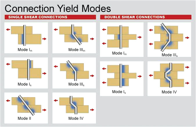
Dowel-type connection yield modes.
Yield equations have been developed for each mode relating the joint load to the maximum stresses in the wood members and the fastener. The capacity of the connection under each yield mode is keyed to the bearing strength of the wood under the fastener and the bending yield strength of the fastener, with the lowest capacity calculated for the various modes taken as the reference design value for the connection. Four limiting yield modes characterized by the NDS equations include:
- MODE I: bearing-dominated yield of wood fibers
- MODE II: pivoting of fastener with localized crushing of wood fibers
- MODE III: fastener yield in bending at one plastic hinge and bearing-dominated yield of wood fibers
- MODE IV: fastener yield in bending at two plastic hinges and bearing-dominated yield of wood fibers
Subscripts “m” and “s” denote main member and side member, respectively. Accordingly, Mode Im represents the case where the main member controls by bearing-dominated yield of wood fibers, whereas Mode Is is side member controlled. Mode III is similarly characterized.
The dowel bending yield strengths, Fyb, of bolts are given in NDS Appendix I. For A36 and stronger steels, Fyb equal to 45,000 psi is a conservative value and is equivalent to the bolt strength reported in the original bolt test research used to develop the methodology. For detailed technical information on lateral design equations, see AWC’s Technical Report 12: General Dowel Equations for Calculating Lateral Connection Values available at www.awc.org.
Spacing, End, and Edge Distance
For dowel-type fasteners with diameters equal to or greater than ¼ inch, the geometry factor, C∆, provides a proportionate reduction of reference lateral design values for less than full end distance or less than full spacing distance. The lowest geometry factor for any fastener applies to all other fasteners in that same connection, not just to the end fastener or a pair of fasteners in a row. It should be noted that further reductions may be necessary when checking stresses in members at connections
For parallel or perpendicular to grain loading, limiting the maximum distance between outer rows of fasteners on the same splice plate to 5 inches avoids splitting that could occur in members at connections as a result of restraint of shrinkage associated with drying in service (structural glued laminated timber has different limits). Special detailing can be utilized in cases where distances between outer rows of bolts exceed the limits in 2015 NDS 12.5.1.3, such as the use of multiple splice plates or a single splice plate with slotted holes to allow shrinkage.
Local Stresses in Fastener Groups
Where a fastener group is composed of closely spaced fasteners loaded parallel to grain, the capacity of the fastener group may be limited by wood failure at the net section or tear-out around the fasteners caused by local stresses. The capacity of connections with closely spaced, large diameter bolts has been shown to be limited by the capacity of the wood surrounding the connection. Connections with groups of smaller diameter fasteners, such as typical nailed connections in wood-frame construction, may not be limited by wood capacity. The 2015 NDS Section 11.1.2 states that “Local stresses in connections using multiple fasteners shall be checked in accordance with principles of engineering mechanics. One method for determining these stresses is provided in Appendix E.” NDS Appendix E includes provisions for calculating net section tension capacity, row tear-out capacity, and group tear-out capacity.
Bolt Design Example
Determine the ASD capacity of a tension splice shown in Figure 2 with the following assumptions:
- Assume 1-inch diameter x 5-inch long bolts
- 2×12 No. 2 Southern Pine main and side members (see Table 1 for design values)
- Dead and construction live load controls
- Normal moisture and temperature conditions
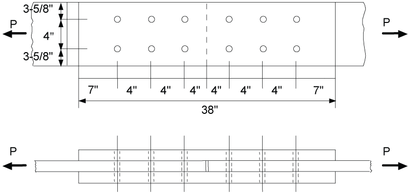
Figure 2. Bolted tension splice example.
Adjustment Factors
First, determine applicable adjustment factors based on assumed conditions. NDS Table 11.3.1 provides a clear and concise overview of applicable adjustment factors for connections. Of the eight dowel-type connection adjustment factors applicable for ASD, only five have potential applicability to this example (as highlighted in Figure 3). Since two of the assumptions are a normal moisture and temperature environment, the wet service factor, CM, and the temperature factor, Ct, are both unity.
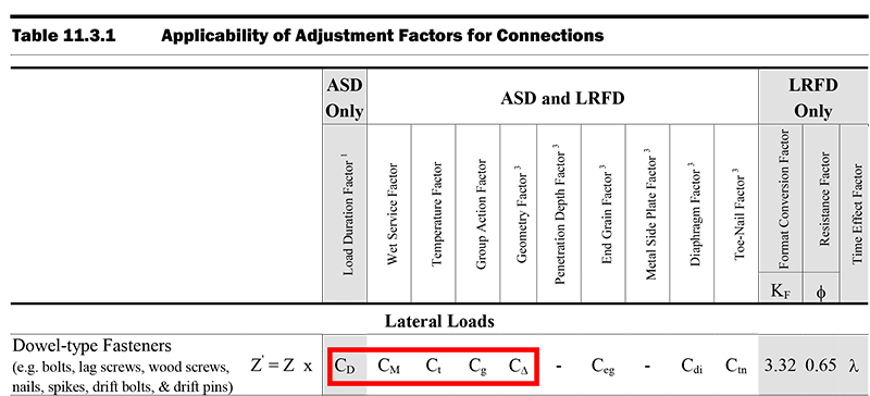
Figure 3. Excerpt of 2015 NDS Table 11.3.1 connection adjustment factors for dowel-type fasteners. Note: See actual NDS table for full details of superscript reference.
The load duration factor, CD, accounts for wood’s unique ability to carry substantially greater maximum loads for short durations than for long durations. Based on the assumption of the dead and construction live load combination controlling, the seven-day load duration factor of 1.25 is applicable per NDS 2.3.1.
The group action factor, Cg, accounts for load distribution within a fastener group. Tests of bolted connector joints have shown that the load capacity of connections containing multiple fasteners in a row is not directly proportional to the number of fasteners, with those located near the ends of the row carrying a greater proportion of the applied load than those located in the interior of the row. Section 11.3.6 of the 2015 NDS provides both a calculation method and tabulated values. For this example and using NDS Table 11.3.6A, since the gross cross-sectional area of the side members (As = 2×16.875 in2) is twice that of the main member (Am = 16.875 in2), the ratio Am/As = 0.5 is used with As = 16.875 per footnote 1 (Figure 4). The interpolated value is Cg = 0.97.
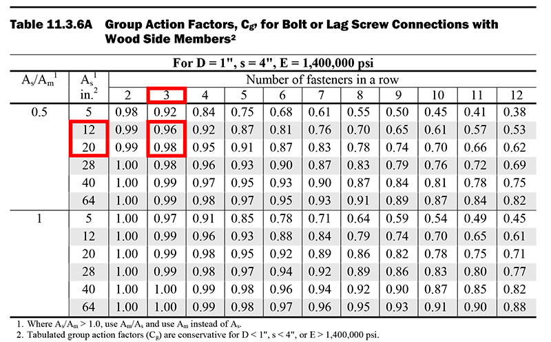
Figure 4. Excerpt from NDS Table 11.3.6A group action factors for bolts with wood side members. Note: See actual NDS table for full details of superscript reference.
As discussed earlier, the geometry factor, C∆, provides a proportionate reduction of reference lateral design values for less than full end distance or less than full spacing distance. Table 2 provides a summary of end and edge distance, spacing assumptions and respective adjustment factors based on NDS requirements.
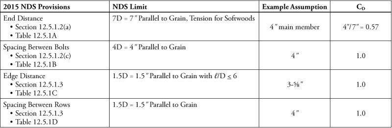
Table 2. Applicable geometry factors for example assumptions.
Yield Limit Values
Section 12.3 of the 2015 NDS provides the methodology for calculating reference lateral design values for dowel-type connectors. For double shear connections, only four yield limit equations apply. Using NDS Table 12.3.1A and Equations 12.3-7 through 12.3-10, the four calculated yield values are:
Im = 2306 lbs Controls
Is = 4612 lbs
IIIs = 4307 lbs
IV = 6003 lbs
As noted earlier, the lowest capacity calculated for the various yield modes is taken as the unadjusted reference lateral design value, Z, for the connection. Therefore, Z = 2306 pounds.
Note that the NDS also tabulates bolt design values based on the yield limit equations. Figure 5 shows the selection of the applicable reference lateral design value from 2015 NDS Table 12 F. Note that tabulated values are rounded to the nearest 10 psi.
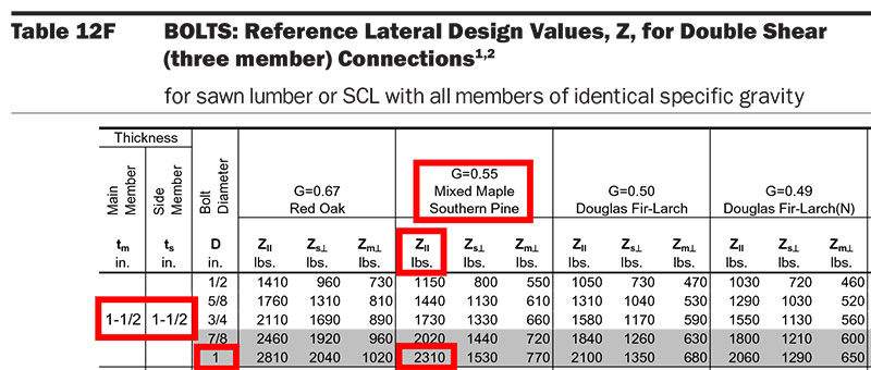
Figure 5. Excerpt of 2015 NDS Table 12F for selection of applicable reference lateral design value for double shear wood-to-wood bolted connections. Note: See actual NDS table for full details of superscript reference.
Note also that a free online connection calculator and corresponding apps for smartphone and tablet devices is available on the AWC website. It allows calculation of the various yield modes for determining reference lateral design values.
Adjusted Multiple Bolt Capacity
The next step is to calculate the adjusted multiple bolt capacity using the reference lateral design value and all applicable adjustment factors. NDS nomenclature uses the prime symbol to denote adjusted design values, therefore the equation becomes:
Z‘ = n Z CD Cg C∆
= (6)(2306)(1.25)(0.97)(0.57)
= 9,562 lbs
where: n = number of bolts on each side of the splice
Local Stresses in Fastener Groups
The final step in the process is to check net section requirements around the group of fasteners. Using NDS Appendix E, check capacities for net section tension, row tear-out, and group tear-out. To accomplish this, design values for tension and shear as shown in Table 1 are used. Similar to bolt design, these reference design values are modified by applicable adjustment factors for end use. For this example, the only applicable adjustment factor is the load duration factor, CD = 1.25. See NDS Appendix E for the definition of terms not clarified here.
Net Section Tension Check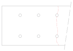
- ZNT‘ = Ft‘ Anet (2015 NDS Equation E.2-1)
- Ft‘ = 450(1.25) = 562.5 psi
- Anet = 13.7 in2
- ZNT‘ = 7,706 lbs
Note: Hole size for the net area includes 1/16-inch oversizing per 2015 NDS 12.1.3.2.
Row Tear-Out Check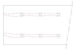
- ZRTi‘ = ni Fv‘ t scritical (2015 NDS Equation E.3-2)
- ni = 3
- Fv‘ = 175(1.25) = 219 psi
- t = 1.5“
- scritical = 4“
- ZRTi‘ = 3,938 lbs for one row
- ZRT‘ = 7,875 lbs for two rows
Note: scritical is the minimum of the end distance and the in-row bolt spacing = 4 inches.
Group Tear-Out Check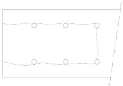
- ZGT‘ = ZRT1‘/2 + ZRT2‘/2 + Ft‘ Agroup-net (2015 NDS Equation E.4-1)
- ZRT1‘ = ZRT2‘ = 3,938 lbs
- Ft‘ = 450(1.25) = 562.5 psi
- Agroup-net = 4.41 in2
- ZGT‘ = 6,418 lbs
Note: Hole size for the net area includes 1/16-inch oversizing per 2015 NDS 12.1.3.2.
Final Bolt Capacity
Comparing adjusted net section capacities to the adjusted multiple bolt connection capacity reveals that group tear-out capacity controls at 6,418 lbs:
Adjusted Multiple Bolt Capacity Z‘ = 9,562 lbs
Net Section Tension Capacity ZNT‘ = 7,706 lbs
Row Tear-Out Capacity ZRT‘ = 7,875 lbs
Group Tear-Out Capacity ZGT‘ = 6,418 lbs Controls
Trade-offs
Although counter-intuitive, for this particular example, decreasing the bolt diameter increases the capacity of the connection. Specifically, changing the bolt diameter to ¾ inch results in an adjusted multiple bolt capacity of 7,174 lbs, but the group tear-out capacity increases to 6,627 pounds.
Modification of fastener placement within a fastener group can also be used to increase row tear-out and group tear-out capacity limited by local stresses around the fastener group. Increased spacing between fasteners in a row is one way to increase row tear-out capacity. Increased spacing between rows of fasteners is one way to increase group tear-out capacity. However, as discussed earlier, 2015 NDS Section 12.5.1.3 limits the spacing between outer rows of fasteners paralleling the member on a single splice plate to 5 inches. This requirement is imposed to limit local stresses resulting from shrinkage of wood members. Where special detailing is used to address shrinkage, such as the use of slotted holes, the 5-inch limit can be adjusted.
By increasing the spacing between bolt rows, srow, in the example to 5 inches, the group tear-out capacity is increased. Table 3 reveals trade-offs that can be used in the example to increase the joint capacity based on the limits discussed. A 7/8-inch bolt with 5-inch spacing between rows provides a capacity of 7,365 pounds, the optimal value for this particular configuration without special detailing.
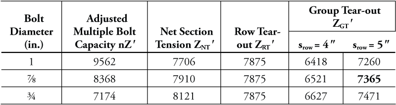
Table 3. Trade-offs for bolt design values vs. net section capacities (lbs).
Conclusion
Connection design is an iterative process that sometimes requires trade-offs. Bolt design per the 2015 NDS is not just a matter of selecting a design value from a table. In addition to the yield limit equations for dowel-type connections, application of spacing, end, and edge distance requirements for connections and provisions related to bolt design including local stresses in fastener groups must be considered. Due to the anisotropic nature of wood, consideration for load direction relative to grain orientation and moisture effects are essential. Good connection design for wood considers all of these factors.▪