
Synergy of Art and Function
The Cottonwood Cornerstone Center office building complex has risen from the depths of an ancient lake, through the gravel shores, and sits on the remnants of a reclaimed gravel pit. Land with panoramic views is valuable even if the site is unusually difficult to build on. Undeterred, the client brought together a design team that would explore and evaluate options so that a signature structure, which complements the beautiful natural surroundings and community, could be built. The result of those efforts was an aesthetically pleasing work environment for the tenants, and an efficient and cost-effect structural solution to a very challenging site and strict design parameters.
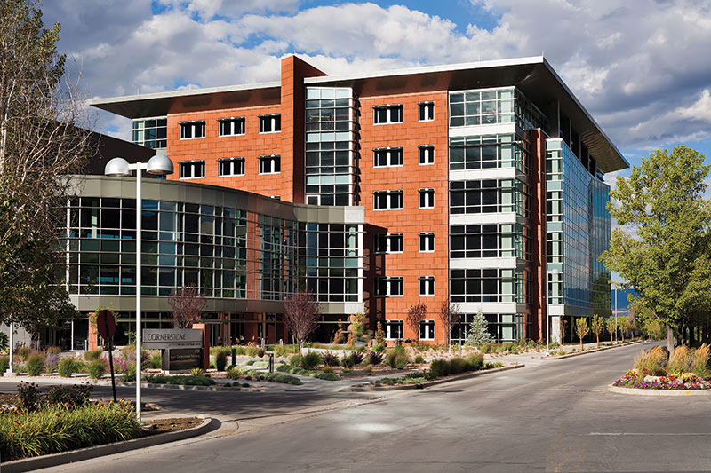
Figure 1. Office building complex.
The Cottonwood Cornerstone Center office building complex is located in the shadows of the Wasatch Mountains and less than 1 mile from the Wasatch Fault. The office building consists of a six-story steel structure, a three-story lobby connector steel structure (Figure 1), and a two-story parking garage with conventionally reinforced concrete slabs and post-tensioned concrete beams. The engineering design of this elegant Class A office building complex provided some unique challenges due to local soil conditions, high seismic forces, the owner’s desire for a shallow structural depth, a curved cantilevered lobby walkway, and a light gauge steel stud façade framing, supporting expensive imported cut sandstone with horizontal seismic slip joints at each floor.
Varying Soil Conditions
About 25,000 years ago, Lake Bonneville covered the Salt Lake Valley with its shores nestled up against the Wasatch Mountains. Over time, sediment and gravel layers were deposited along the shoreline. The geotechnical report provided the following background of the site: “For many decades, the Cottonwood Corporate Center site was utilized as a working gravel pit. During the early 1990s, it was decided to terminate the gravel pit operations, reclaim the area, and ultimately develop the reclaimed areas as a part of an extensive office park.”
Numerous borings on the site revealed that non-engineered fill was used as part of the reclamation of the site. The fill varies in depth from 3.5 feet to 25 feet. All of the non-engineered fills exhibited variable and, in most cases, poor to very poor engineering characteristics. The geotechnical engineer provided three soil preparation options that use conventional spread footings and continuous wall foundations.
- Bear the foundations on suitable natural soils
- Replace granular fill extending to suitable natural soils
- Improve the granular fill through the installation of Geopiers®/stone columns
The basement space under the six-story building was utilized for parking and mechanical equipment. The space was divided into two areas; a 19-foot 6-inch deep mechanical basement and an 11-foot 4-inch deep parking garage. At the deeper basement, the excavation extended down into native soils allowing the use of conventional spread and spot footings. However, in the parking garage, the native soil was at least 10 feet below the bottom of the footings. Rather than over excavate down to the native soil, the design team decided to use Geopiers/stone columns to improve the bearing capacity of the non-engineered fills.
Some of the soil could not be improved enough with Geopiers/stone columns to support the 910-kip column loads due to the presence of moderately sized cobbles and small boulders. It was decided that at four column locations, steel “H” piles would be used to penetrate through the inadequate soil and into the strong native soils below. The design team became concerned that differential settlement might be an issue due to the use of shallow footings, Geopiers, and deep foundations. The geotechnical engineer indicated that the settlements for foundations on native soil and foundations on improved soil would essentially be the same. After receiving the “H” pile depths and loads, the geotechnical engineer was able to calculate a differential settlement of less than ½ inch between the “H” pile system and the spread footings. The footings and foundations were designed and reinforcement detailed to accommodate this small differential settlement without damaging the foundations or architectural finishes.
High Seismic
This building complex is located in a high seismic region and was designed using an Ss value equal to 1.572g and S1 value equal to 0.634g, with a soil site classification of D. The design team faced the challenge of meeting the owner’s desire for a “brace-free space” to obtain unobstructed views while avoiding the premium in cost associated with a conventional steel moment frame system. What made matters more challenging was the client-imposed beam depth limit of 24 inches. To solve these problems and do so in an economical way, the design team evaluated numerous structural systems and determined the most cost effective steel solution was special steel moment frames utilizing the increased stiffness of the SidePlate Connection Technology (Figure 2).
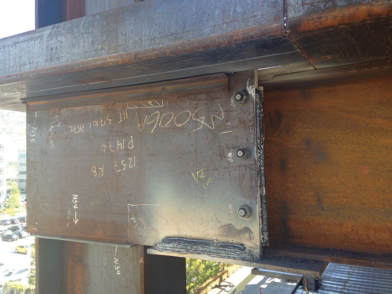
Figure 2. SidePlate connection.
When comparing the various lateral systems, the design team determined that, to meet the allowable 0.02h code-mandated drift requirement, a conventional moment frame system such as a Reduced Beam Section (RBS) would have required the use of W24x131 beams and W24x370 columns. Utilizing the SidePlate system, the final beam sizes were W24x94s, and the final column sizes were W24x192s. As required per the seismic provisions, each joint was designed to resist the probable maximum moment of the beam taking into account specific hardening ratios. For these particular joints, the design moment was equal to 1455 k-ft.
The estimated cost savings associated with the decision to use SidePlate was substantial. Based on the steel tonnage reduction of 154 tons (1.47 psf) and the simplified shop and field fillet welding used in the SidePlate system, the net cost savings to the project, after the SidePlate licensing fee was paid through the steel fabricator, was approximately $375,000. In addition to the steel package savings, the owner benefited from savings in ultrasonic testing due to the elimination of full joint penetration welds. When added together, the savings brought to the project by the design team’s decision to use the SidePlate Connection Technology was over $400,000 or $2 per square foot.
By working closely with the designers at SidePlate, the design team was able to provide the open layout the owner desired without the cost premium associated with conventional moment frame systems.
Minimal Beam Depths
The owner wanted to provide tenants with high ceilings while limiting the floor-to-floor height to 13 feet 6 inches. Limiting the floor-to-floor height also had the added benefit of minimizing the overall building height and reducing the amount of costly architectural finishes. Typically plumbing loops and mechanical ducts run below the structural framing, but the design team chose to penetrate the main steel girders with these elements. For this approach, the W30x108 composite steel girders were designed using the American Institute of Steel Construction’s (AISC) Design Guide #2 with a 12-inch by 12-inch web opening for the plumbing loop and a 12-inch by 34-inch web opening for the main duct loop (Figure 3). This coordinated effort produced potential ceiling heights of 11 feet without affecting the structural performance of the floor system or resulting in problematic vibrations.
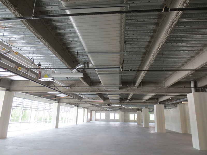
Figure 3. Steel girder web openings.
The size of the web openings were well coordinated with the size of the pipes and ducts, but during construction, it was revealed that the pipes required an insulation wrap which had to be compressed at the openings in the beam web. Although the pipes and duct sizes were discussed and coordinated during design, only the rough duct and pipe sizes were provided, and no mention was made regarding insulation thickness or the need to have larger openings. When penetrating beam webs with ducts and pipes, the design team learned that it is essential to know the total required opening size and not just the duct and pipe size.
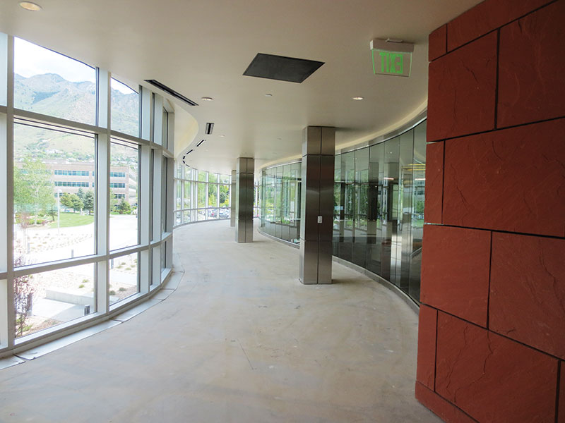
Figure 4. Curved lobby walkway.
Curved Cantilevered Lobby Walkway
The two-story lobby is a beautiful synergy of interior art and majestic mountains viewed through the second story curved glass walkway (Figures 4 and 5). The curved walkway was created using 5/16-inch thick bent plate edge angles supported by L3x3x¼ kicker braces aligned with the W12x19 floor beams. At other locations, the walkway floor framing was hung from the third floor to create an open lobby area below. Because the connector experiences high levels of human traffic, vibration control and floor stiffness were a primary focus of the design of the cantilevered floor systems.
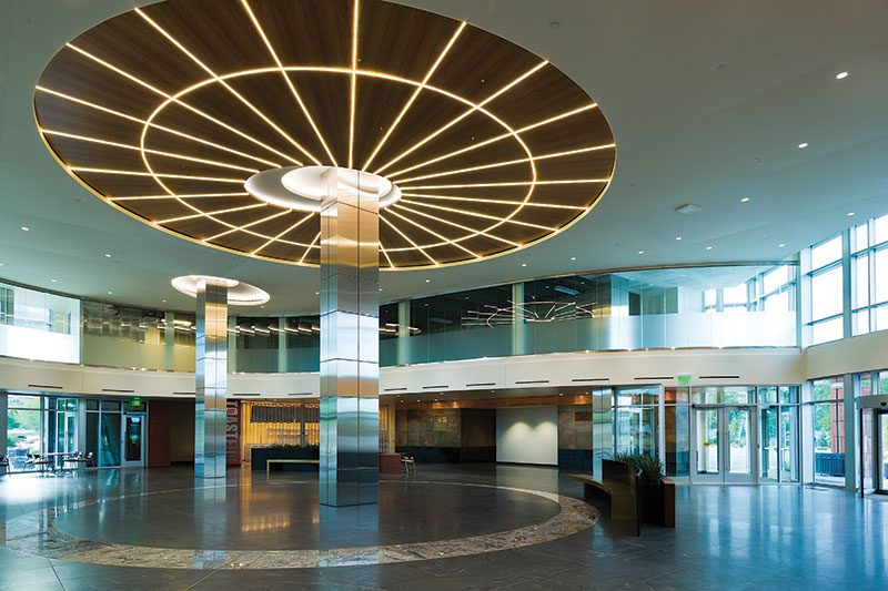
Figure 5. Two-story lobby.
Design details showed the mullions of the curved window system bearing on top of the curved light gauge track. Typically this is not an issue with a straight wall and a stiff track, but, in this case, the flanges and webs of the tracks were cut to produce the curve. Because the track was cut, the stiffness of the track was significantly reduced causing the window system to sag. Additional studs aligned with the window mullions were installed and attached to the structure to provide a stiff support system which prevents the framing from sagging and provides adequate support for the windows.
Façade Framing
The façade of the building is a balance of floor to ceiling windows and punched openings surrounded by cut sandstone (Figure 6). There were many challenges in the design of the façade framing which included allowances for vertical deflection between floors due to gravity loads, allowances for horizontal movement between floors due to seismic and wind loads, and supporting the roof overhang framing )often referred to as “The Sombrero” by the design team).
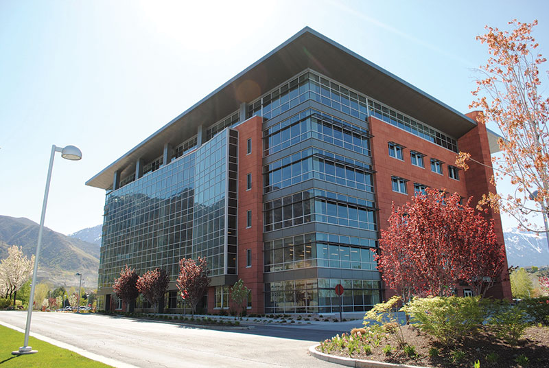
Figure 6. Cut sandstone façade and full height windows.
The cut sandstone was carefully selected and quarried from India. The sandstone was a large lead item that had to be carefully coordinated so that material could be harvested and shipped to avoid the monsoon season. Needless to say, great care was taken to design a stiff framing system to protect and support this beautiful stone. A vertical deflection criterion equal to ¾ of an inch was used to design the perimeter beams supporting the stone clad walls. A vertical gap was designed into the façade framing just below each floor at the tops of the floor-to-ceiling window systems. This gap in the façade framing was accomplished using a 2½-inch deep 16 gauge deflection track with a 1-inch gap between the track and top of the stud. The track and wall framing above the joint were attached to the floor slab edge angle and braced back to the steel structure. To allow for vertical movement, it was critical to clarify that the Densdeck must not be attached to the track, but could be attached to the stud below the joint (Figure 7).

Figure 7. Vertical and horizontal slip joint detail.
A horizontal slip joint was designed into this same detail to allow each floor to move independently during a wind or seismic event. The typical façade framing consisted of 600S162-54 studs spaced at 16 inches on center. The 2½-inch deep track above the joint provides the out-of-plane resistance at the top of each stud. The stud wall with Densdeck below the joint is not attached to the deep track and, therefore, can slide in the plane of the wall inside the deep track.
The geometry of the “Sombrero” was designed to cantilever 5 feet past the steel beam structure and maintain a 21-inch fascia depth. 362S162-54 studs spaced at 16 inches on center were utilized to form the roof and soffit framing. Both the roof light-gauge framing members and the soffit light-gauge framing members cantilever over the steel beam to provide a redundant cantilever support system (Figure 8).
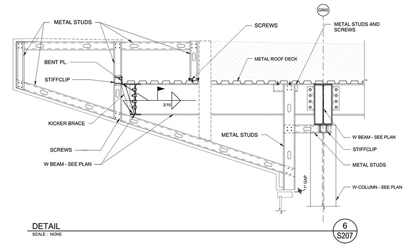
Figure 8. Sombrero light gauge framing detail.
Conclusion
The Cottonwood Cornerstone Center office building was challenging for many reasons, but the success of the project reinforced the importance of clear communication between the owner, design team, geotechnical engineers, contractor, subcontractors, and suppliers. The key to the success of this project was that open communication was encouraged throughout the design and construction project, thus providing an avenue to exchange and explore new ideas which ultimately resulted in a quality and cost-effective project.▪
Project Team
Owner: Cottonwood Partners
Structural Engineer of Record: ARW Engineers, Ogden, UT
Architect: Arch Nexus, Salt Lake City, UT
Contractor: Big-D Construction, Salt Lake City, UT
Specialty Structural Engineer: SidePlate Systems, Inc, Mission Viejo, CA