
As one of the major East-West traffic corridors into downtown Seattle, WA, the SR520 Floating Bridge and Landings (SR520 FB&L) spans Lake Washington. The pontoon design for the floating span was discussed in the October 2016 issue of STRUCTURE magazine. The floating span is dynamic, moving with fluctuations in the water level of the lake as well as wind and wave action. As a result, each end of the bridge requires a transition span from the floating bridge portion to the fixed, land-based approaches.
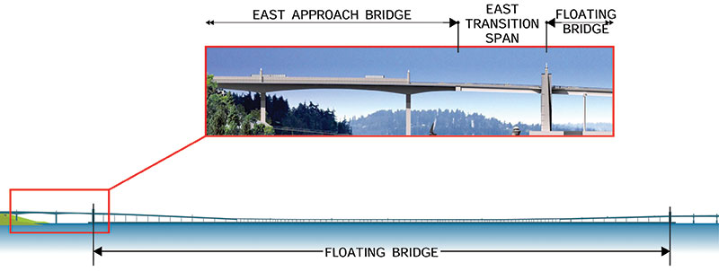
Figure 1. Plan/elevation schematic of transition spans.
Figure 1 illustrates the eastern transition span; the west end is supported by Pontoon W of the floating bridge, and the east end is supported by a cantilever of the eastern approach. Similarly, the west transition span is supported by Pontoon A on one end and by Pier 36, a land based fixed pier, at its other. Westbound and eastbound traffic lanes are located on separate superstructures; thus, 4 transition spans in total were needed: two each on the east and west ends of the floating span. Each transition span is approximately 190 feet long and consists of a series of 8-foot deep, I-shaped steel plate girders.
Design Motions
The design motions for the pontoons were based on the wind-wave analyses conducted by the Washington Department of Transportation’s (WSDOT) naval architect. Design motions, in addition to standard bridge movements, include:
- Fluctuations in the lake water elevation: The water elevation is regulated by the Ballard Locks and results in a plus/minus 2-foot fluctuation in lake water elevation annually. In extreme cases, the design considered mooring failures in a 20 and 100-year storm, and also a failure of the Ballard Locks, which might result in a 20-foot drop in the lake water level.
- Lateral sway of the bridge: In a storm event, the transition span needed to accommodate a 2-foot lateral sway in the floating bridge position at each supported end.
- Roll of the pontoons: Due to wind and wave action, the floating bridge rolls about its longitudinal axis, for which the transition span needed to twist to accommodate the rolling motions and prevent the steel plate girders from lifting off of the bearing supports.
As for the standard bridge movements, the transition span needed to accommodate over 6 feet of total longitudinal motion at the end.
Transition Span Concept
Common practices by designers of mechanical equipment include improvements to existing successful concepts rather than developing new ones, the reason being that it is often difficult to recognize all the potential problems that may be inherent in a new concept. The analogy of machine design is relevant to the transition spans of the SR520 FB&L project because the transition spans must articulate movement in many directions without adversely affecting the serviceability of the transition spans or the supporting structures.
The design storm, seismic loads, and expected motions on the project significantly exceed the demands of other floating bridges currently in service in the State of Washington. Applying transition span concepts utilized for other floating bridge designs could not work on this project due to their high torsional stiffness. With these motions, a torsionally stiff deck results in deck liftoff at one corner of the transition spans under the design pontoon roll. Consequently, a new bearing concept, ultimately termed the “trailer hitch,” was developed, which was more robust, economical, and provided true six degrees of freedom movement capability. One of these degrees of freedom is provided by the torsional flexibility of the span, which had to be adequate to prevent corner liftoff.
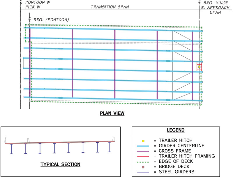
Figure2. Transition span framing plan (East North; others similar).
As illustrated in Figure 2, the east transition-span utilized an open soffit design, consisting of torsionally flexible steel I-beams pinned-supported at the approach by the trailer hitch, and roller-supported on the pontoon end; that is, girder stops restrain transverse movement but are free to slide longitudinally.
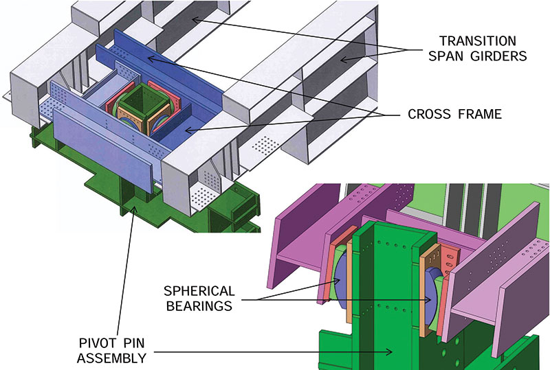
Figure 3. Trailer hitch schematic.
Trailer Hitch
The trailer hitch is a built-up steel weldment shown schematically in Figure 3 and pictured in Figure 4. As shown in Figure 3, the embedded portion of the trailer hitch has flanges which house high strength post-tensioning rods that anchor the trailer hitch to the approach span. The exposed portion of the trailer hitch is box-shaped with spherical bearings on each face. The spherical bearings share a common radius, essentially forming a sphere, and act similar to an automobile trailer hitch. Figure 4 shows the steel plate girders being set over the trailer hitch.
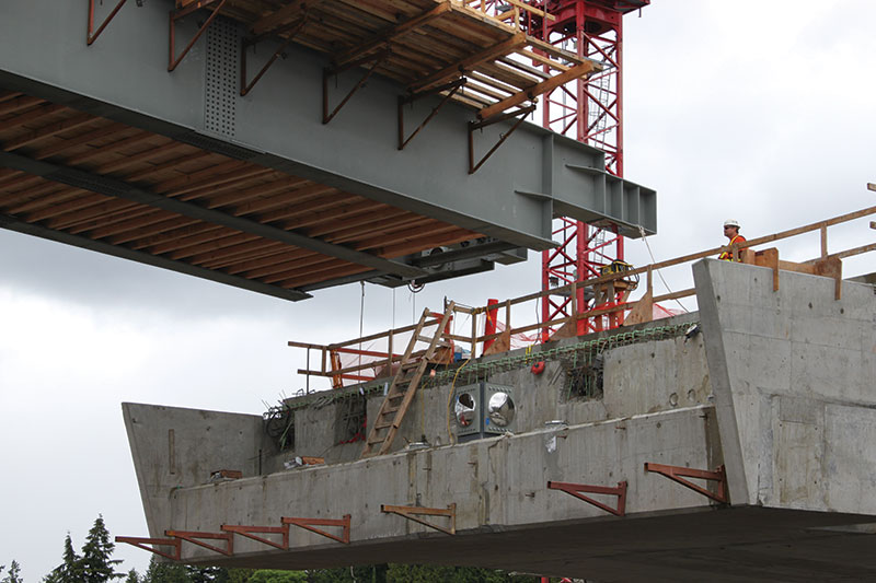
Figure 4. Girders being erected over the trailer hitch.
Kinematics of the Transition Span
The kinematics of the West and East transition spans are mirror opposites in behavior while the South and North spans have nearly identical movement, differing mainly in deck width. As a result, discussion of kinematics focuses only on the East span.
Teflon-lined spherical bearings provide vertical support at each girder end. Since the pontoon is free to slide longitudinally, long Teflon sliders were mounted to the underside of the girder bottom flanges at the pontoon end. This configuration was needed to accommodate the design motions, including rotations about the vertical axis due to flexural deformations of the floating span. HDPE-lined girder stops provide transverse lateral restraint to the pontoon. The girder stops were configured to allow free rotation about a central vertical axis at the pontoon end. At the East end of the span, longitudinal and transverse restraint is provided by the trailer hitch post which is mounted on the cantilevered end of the approach span. The side mounted spherical bearings on the trailer hitch post allow free rotation about the central vertical axis. Short sliders at each girder’s spherical bearing accommodate vertical axis rotation at the east end of the span.
The center-of-curvatures of the four spherical bearings on the trailer hitch post align with an axis of rotation of the spherical bearings on the girder ends located on the approach span. Similarly, the center-of-rotation of the spherical bearings on the girder ends located at Pontoon W, at the baseline neutral pontoon elevation position of the pontoons, were located on a line parallel to the bearing center-of-rotation line at the approach span end, so that the span can accommodate pontoon heave without binding (Figure 5).
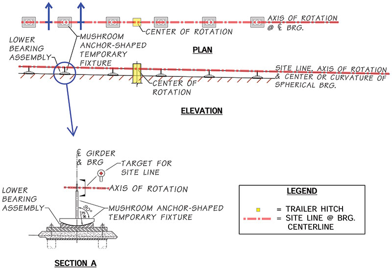
Figure 5. Temporary target for aligning girder bearings with trailer hitch bearings.
The lower half (concave plates) of the spherical bearings for each girder end were set plumb on individual pads following the transverse slope of the roadway. The trailer hitch post was set plumb. The centers-of-curvature of all four convex plates on the trailer hitch post were adjusted so as to be coincident with each other and the line through the axis-of-rotation of the girder bearings.
Torsional Flexibility of the Transition Span
So as to not disrupt the driving surface with deck lifting at the expansion joint during pontoon motion, the deck of the transition span had to be sufficiently flexible in torsion. Flexibility was achieved by using steel I-section girders with no bracing along the girder bottom flanges and transverse diaphragms only at the ends, quarter points, and mid-span.
The transition spans were analyzed using a finite element model (FEM). The FEM model with solid end diaphragms comprised an open-bottom and closed-top box. The transition span was analyzed for the worst-case service load condition associated with pontoon storm roll and zero live load. In the FEM model, a comparison was made between the uncracked and cracked (a concrete modulus reduced by 50%) bridge deck stiffness. It was determined that the deck had only a nominal influence on the torsional stiffness. The most significant factors contributing to the torsional deck stiffness were the inclusion/omission of the end and intermediate diaphragms. With the selected transition span configuration, the compression reaction was approximately 50 kips under the worst-case service load condition.
Construction
The spherical girder bearings were aligned by sighting a laser along the axis of rotation. As shown in Figure 5, a mushroom-shaped temporary fixture, machined to fit the lower concave bearing plates with a target on the end of a shank to locate the center-of-curvature, was plumbed in place. Screw jacks on the lower bearing plate were used to adjust the bearing center-of-rotation to match the laser line.
A hole through the trailer hitch and bearings allowed the same laser line to define the location of its center-of-rotation. Once the girder lower bearing elements were positioned relative to the trailer hitch bearings, the girder grout pads were cast and cured, and then the girders were set transversely plumb with their individual convex plates and sliders on the previously erected lower halves of the girder bearings (Figure 5).
The girders were erected in pairs, at a minimum, with the end diaphragm and trailer hitch framing beam installed. The uphill trailer hitch convex spherical bearing assembly was loose fit to the framing beam. The uphill bearing on the trailer hitch post keeps each span from sliding down onto the pontoon. The bearings could be adjusted up and down, and sideways, to locate its center-of-curvature coincident with the site line. Once the girders were set on their bearings, the uphill post spherical bearings were locked into position, allowing the approach bridge end of the span to rotate freely about the sloped line of the girder bearings.
The downhill trailer hitch spherical bearings could be adjusted the same way; however, they were only snug fit to avoid jamming when the span rotates. The trailer hitch bearings aligned with the cross slope were adjusted the same way as the longitudinal bearings.
By accommodating these transition span movements, the SR520 Floating Bridge spanning Lake Washington can remain serviceable even under extreme weather events.▪