
A Novel Lightweight Solution for Long-Span Bridges
Orthotropic steel decks (OSDs) have been used commonly in long-span bridges to reduce self-weight, and therefore improve the spanning ability of these bridges. The OSDs are usually covered with a 2- to 3-inch-thick asphalt wearing course. Under cyclic heavy traffic loads, these steel decks are susceptible to fatigue cracks, while asphalt overlays can suffer from cracking and shoving problems. Both issues compromise the serviceability and durability of the bridge deck.
Over time, some countermeasures have been proposed to address these problems, including increasing the thickness of deck plates, refining the configuration of fatigue-prone details, and enhancing the welding quality. However, none of these approaches have proved to be very effective since none of them provide many benefits for increasing the stiffness of the deck plate. Recently, Buitelaar et al. (2004), Murakoshi et al. (2007), and Dieng et al. (2013) have proposed to use a reinforced high performance concrete (RHPC), a steel-fiber-reinforced concrete (SFRC) overlay and a fiber-reinforced UHPC (UHPFRC) layer, respectively, to strengthen the stiffness of the steel deck. However, these attempts did not achieve satisfactory results. Cracks developed in the RHPC and SFRC while sliding occurred between the steel deck and UHPFRC layer. The reason was either that the concrete did not have sufficient cracking strength, or the concrete layers did not develop sufficient composite action with the steel deck.
Proposed Steel-UHPC Lightweight Composite Deck (LWCD) System
To systematically address the issues above, Prof. Xudong Shao’s research group at the Hunan University introduced a novel lightweight composite deck (LWCD) system. The LWCD is composed of a conventional OSD covered by a 1.38- to 2.36-inch-thick (35-60 mm) UHPC layer (Figure 1). The OSD and UHPC are connected through headed studs to ensure that the desired bonding performance of full composite action could be achieved between the two structural components. In the LWCD, the UHPC layer functions as a structural component and is designed to have the same service life as that of the OSD. To ensure the desired cracking strength and fatigue performance, the UHPC is compactly reinforced with a steel mesh, as shown in Figure 1.
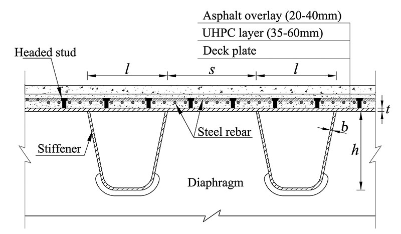
Figure 1. Schematic of the LWCD.
A substantial amount of research in the past six years has explored the fundamental behaviors of the LWCD, including the material property of the UHPC, shear performance of the shear studs, static and fatigue performance of the LWCD. Some of these studies are briefly introduced in the following sections.
Behaviors of LWCD
The Humen Bridge, a suspension bridge that has a main span of 2,913 feet (888 m) and was opened to traffic in 1997 in Guangdong, China, was selected as the test bed for evaluating the performance of the proposed LWCD. Bridge deck segments and longitudinal deck strips were fabricated and tested in the laboratory. Finite element (FE) analysis was also performed to develop the field testing plan.
Static Performance
The performance of the LWCD under the design vehicle loads specified in the General Code for Design of Highway Bridges and Culverts in China (MTC 2004) was investigated based on the FE analysis using the ANSYS program. The performance of a standard OSD without UPHC layer was also studied for the purpose of comparison. The main dimensions of the cross section are as follows: t = 0.47 inch, b = 0.31 inch, h = 10.31 inches, s = 12.05 inches, l = 12.36 inches (t = 12 mm, b = 8 mm, h=262 mm, s = 306 mm, l = 314 mm) (refer to Figure 1). The UHPC layer was 1.77-inch (45 mm) thick. Steel rebars with 0.39-inch (10 mm) diameter were arranged in both directions with a center-to-center spacing of 1.48 inches (37.5 mm). The stress levels at the six typical fatigue-prone details in the steel deck were examined and compared. The analysis results are shown in Figure 2.
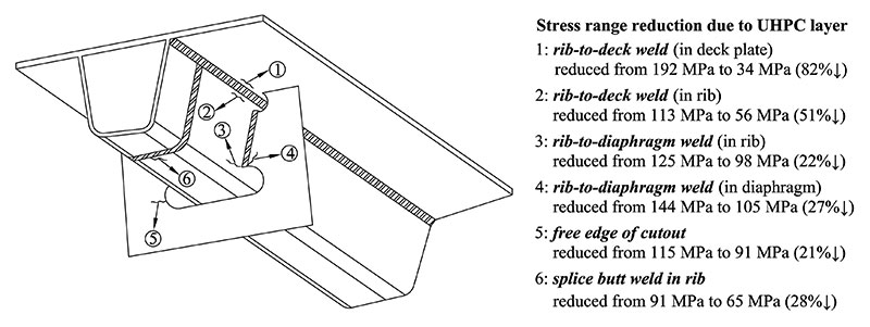
Figure 2. Comparison of stress ranges in fatigue-prone details.
With the addition of UHPC on the steel deck, the stress ranges in all six details of the OSD have been reduced significantly, especially in the rib-to-deck welds where the stresses are reduced by 82% and 51% in the deck plate and rib, respectively. The stress ranges are below the corresponding constant-amplitude fatigue limits (CAFLs) specified in the bridge design codes (European Committee for Standardization 2005), indicating that these details would theoretically not have fatigue problems during their service life.
Performance of Headed Studs
The headed studs used in the LWCD have a height of 1.38 inches (35 mm) and diameter of 0.51 inch (13 mm), resulting in a height-to-diameter ratio of 2.7. Push-out tests were performed to study the behavior of the short-headed studs embedded in the UHPC. The test results show that when the load was increased to a certain value, the headed studs were sheared off from the steel plates while the UHPC layer was intact with no observable cracks developed, indicating that even with a low height-to-diameter ratio of 2.7, the studs could still develop full shear strength in the LWCD.
Performance at Negative Bending Moment Zone
When exposed to traffic loads, tensile stresses develop at the negative bending moment zones on the UHPC layer, e.g. at the diaphragm sections. To reveal the behavior of the UHPC layer under such negative bending moments, a static load test was performed on a steel-UHPC composite beam specimen (Figure 3), which consisted of an OSD strip and a 1.77-inch-thick UHPC layer. In the test, the load was incrementally increased until the sample failed.
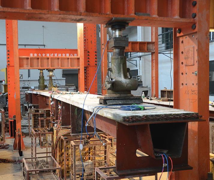
Figure 3. Set-up of the static load test.
The test results show that when the bottom flange of the OSD began to yield due to excessive compression, no visible cracks were observed on the UHPC surface. When local buckling developed at the bottom flange of the OSD at the peak load, cracks with a maximum width of 0.01 inch (0.3 mm) were observed. These observations clearly indicate that the OSD failed before the UHPC layer.
Fatigue Performance
Fatigue tests were also performed on the LWCD specimen. With the compact reinforcement inside, the cracking strength of the UHPC used in this study can reach 6.19 ksi (42.7 MPa) (Shao et al., 2013), as compared to 1.16-1.45 ksi (8-10 MPa) without reinforcement. The fatigue load was set to produce a stress range of 3.09 ksi (21.3 MPa), which is half of the cracking strength at the most critical location of the UHPC layer. The test results showed that the UHPC layer developed no fatigue cracks after 3.1 million cycles at this stress level. Based on FE analysis, the design load only causes a maximum stress range of about 1.45 ksi (10 MPa) in the UHPC layer, indicating that the UHPC layer can meet the design requirements regarding fatigue safety.
Application to Field Bridges
To date, the LWCD has been applied to four bridges in China (Shao et al., 2015), among which the first pilot project was the Mafang Bridge constructed in 1984. This bridge consists of fourteen 210-foot-long (64 m) simply supported spans. Due to the heavy traffic, the pavement suffered from severe deterioration, and cracks were also observed in the OSD. In 2011, a major retrofit was undertaken for the asphalt overlay (Cao et al., 2016). Five different retrofitting schemes utilizing different wearing courses were adopted for the various spans, including a 3.15-inch-thick (8 cm) stone asphalt concrete layer, 3.15-inch-thick (8 cm) epoxy asphalt layer, 3.15-inch-thick (8 cm) sandwich plate, 2.76-inch-thick (7 cm) polymer asphalt concrete layer, and the proposed compactly reinforced UHPC layer (on the 11th span). To examine crack development in the UHPC layer, the first 177 feet (54 m) of the 11th span was covered by a 1.97-inch-thick (5 cm) UHPC layer with a 1.18-inch-thick (30 mm) asphalt overlay on top. The remaining 33 feet (10 m) was covered by a 3.15-inch-thick (8 cm) UHPC layer without an asphalt overlay.
Three routine checks have been performed during the past four years, and no fatigue degradation has been observed in the LWCD. No further crack propagation on the OSD and noticeable deterioration in the asphalt pavement were observed. No cracks were found on the top surface of the 3.15-inch-thick (8 cm) UHPC layer. On the other hand, crack propagations have been observed on the steel decks and severe degradation of the pavement has been seen in decks retrofitted using four other retrofitting schemes approximately 4 years after the installation of decks (Figure 4). Figure 4e is the deck using LWCD, which is entirely damage-free after 4 years. It should be noted that all 5 decks shown in Figure 4 have been subjected to the same traffic loading during the last 4 years.
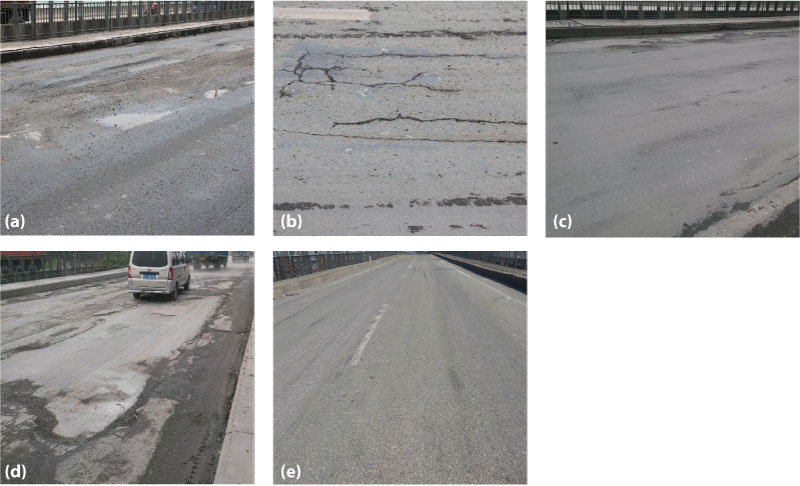
Figure 4. Service state of five retrofitting schemes on the Mafang Bridge after nearly 4 years of service (photos taken in Sep. 2015). (a) Stone asphalt concrete; (b) Epoxy asphalt; (c) Sandwich plate system; (d) Polymer modified asphalt concrete; (e) Proposed LWCD.
Advantages and Potential Use of the LWCD
Field verification of LWCD, compared to other retrofit schemes of the deck shown in Figure 4, indicates excellent potential for the utilization of the LWCD. In summary, the LWCD has the following advantages over the conventional “OSD + asphalt overlay” system:
1) The UHPC layer improves the stiffness of the bridge deck significantly, leading to a considerable reduction in vehicle-induced stresses in the steel deck and therefore a pronounced extension of the fatigue life of the steel deck;
2) The UHPC layer needs no major retrofits or replacement during the service life of the bridge. Therefore, although the LWCD scheme has a slightly higher initial cost compared to conventional schemes that adopt an epoxy asphalt overlay on top of the OSD, its life-long total cost, including costs related to the maintenance and retrofitting of the asphalt overlay, is much (estimated at 85%) lower since the cost of the asphalt overlay in the LWCD scheme is much lower;
3) The weight of the LWCD is comparable to that of the conventional “OSD + asphalt overlay” system. Also, field applications have demonstrated that it is convenient and feasible to construct the LWCD on either a newly-built bridge or an older bridge, making it a very promising deck system for long-span bridges.
Conclusions
In conclusion, the LWCD has shown excellent static and fatigue performance and significant potential for application in long-span bridges. High cracking strength and low permeability of the UHPC layer along with excellent bonding between UHPC layer and steel deck are the keys to ensuring desired performance and durability of the LWCD. Further research should focus on the effects of the following parameters: (1) the ingredients and material ratios, (2) type, shape and volume ratio of the steel fibers, (3) reinforcement ratio of the UHPC, (4) layout of the shear studs, and (5) thickness and size effect of the LWCD specimen on the performance of the LWCD. Also, structural optimization should be pursued to further reduce the cost and to ensure that the stress range levels of the key details are below their CAFLs.▪
Acknowledgements
The authors acknowledge the following funders for their support of this research: the National Natural Science Foundation of China (grant number 51178177), and the Transportation Science and Technology Major Project sponsored by the Ministry of Transport of China (grant number 2011318494160).
References
Buitelaar, P., Braam, R., and Kaptijn, N. (2004). Reinforced high-performance concrete overlay system for rehabilitation and strengthening of orthotropic steel bridge decks. Proc., 1st International Orthotropic Bridge Conference, ASCE, Sacramento, CA, U.S.A, 384-401 (CD-ROM).
Cao, J. H., Shao, X. D., Zhang, Z., and Zhao, H. (2016). Retrofit of an orthotropic steel deck with compact reinforced reactive powder concrete. Struct. Infrastructure Eng., 12(3), 411-429.
Dieng, L., Marchand, P., Gomes, F., Tessier, C., and Toutlemonde, F. (2013). Use of UHPFRC overlay to reduce stresses in orthotropic steel decks. J. Constr. Steel Res., 89(0), 30-41.
Murakoshi, J., Yanadori, N., and Ishii, H. (2007). Research on steel fiber reinforced concrete pavement for orthotropic steel deck as a countermeasure for fatigue. Proc., 23rd U.S.–Japan Bridge Engineering Workshop, Tsukuba, Japan.
MTC (2004). General code for design of highway bridges and culverts (JTG D60-2004). Ministry of Transport of China, Beijing, China, China Communications Press (In Chinese).
Shao, X. D., Cao, J. H., Deng, L., Fan, W., and Zhang, Z. (2015). Orthotropic lightweight steel-UHPC composite deck system. Proc.,4th International Orthotropic Bridge Conference, Tianjin, China, 363-376 (CD-ROM).
Shao, X. D., Yi, D. T., Huang, Z. Y., Zhao, H., Chen, B., and Liu, M. L. (2013). Basic performance of the composite deck system composed of orthotropic steel deck and ultrathin RPC layer. J. Bridge Eng., 18(5), 417-428.
European Committee for Standardization. (2005). Eurocode 3: Design of Steel Structures, Part 1-9: Fatigue (EN 1993-1-9). Brussels, Belgium.