
The new Evergreen Point Floating Bridge, which carries State Route 520 (SR 520), is the world’s longest floating bridge, stretching 7,708.5 feet across Lake Washington in Seattle, Washington. Opened to traffic in April 2016, the bridge replaces the previous SR 520 floating bridge, which was completed in 1963 and had reached the end of its useful service life. The new bridge was constructed in place, adjacent to and just north of the old bridge. Construction of the bridge required a highly-coordinated process to ensure that pontoon freeboard and concrete stresses in the pontoons were maintained within acceptable limits throughout construction.
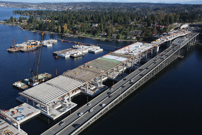
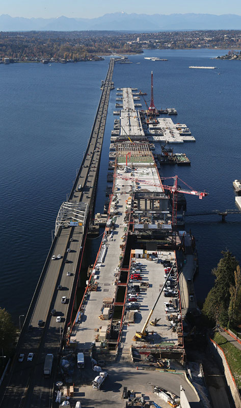
Aerial view of State Route (SR) 520 Evergreen Point Floating Bridge high-rise superstructure under construction.
Floating Bridges of Washington State
Floating bridges have been a major part of Washington State’s infrastructure since 1940 when the first floating bridge was constructed across Lake Washington. Washington is currently host to four of the five longest floating bridges in the world; the William A. Bugge Bridge which crosses Hood Canal (6,521 feet), and three bridges that cross Lake Washington: the Lacey V. Murrow I-90 bridge (6,620 feet), the Homer M. Hadley I-90 bridge (5,811 feet) and the new SR 520 floating bridge (7,708.5 feet). The fourth longest floating bridge is the Demerara Harbor Bridge (6,074 feet) in Georgetown, Guyana.
The original floating bridge over Lake Washington was the brainchild of Homer M. Hadley, an early 20th century Seattle engineer and namesake of one of the two I-90 bridges. His grand scheme of a concrete pontoon floating bridge across Lake Washington is said to have originated from his experience designing barges during World War I. Because of the depth of Lake Washington, over 200 feet in some locations, and very soft soils consisting of thick volcanic ash deposits, traditional bridges have proven too costly to construct.
Bridge Configuration
The new SR520 floating bridge is unique in that the entire roadway is elevated above the pontoons over the full length of the bridge. Other Lake Washington floating bridges utilize the top deck of the pontoon as the driving surface for a majority of the length. The benefit of the elevated roadway is two-fold. First, it keeps vehicles above the lake’s wave spray and splash that occur during large storm events. Second, it provides a maintenance corridor below the elevated roadway that allows maintenance staff access to the pontoons.
The bridge currently has six vehicular lanes and a 14-foot wide bicycle and pedestrian path on the north side. It was also pre-designed for future widening that would allow for the addition of two light rail train lines down the center.
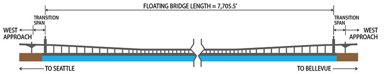
Elevation of the floating bridge.
A precast concrete, segmental, ribbed-superstructure slab post-tensioned in two directions, referred to as the “low-rise”, makes up the center 5,580 feet of the elevated structure. At the east and west ends of the floating bridge, the elevated structure transitions upward to provide for acceptable navigation clearances at the approach structures. This portion of the elevated structure is referred to as the “high-rise” and is comprised of prestressed precast girders with a cast-in-place deck supported on cast-in-place crossbeams and columns. The floating bridge is flanked by 190-foot-long steel I-girder transition spans that connect the floating structure to the fixed land structures. The transition spans and their connections are designed to accommodate all six-degrees of differential movement that can occur between the floating bridge and the fixed approaches.
Pontoons and Ballast
The backbone and floating portion of the bridge are the pontoons themselves, cellular concrete box structures. They were constructed off-lake in Tacoma, WA and Aberdeen, WA and towed to Lake Washington for assembly. A total of 77 concrete pontoons are joined together to complete the floating bridge. There are three types of pontoons: two cross-pontoons, which are added to the ends of the bridge for additional stability and buoyancy; 21 longitudinal pontoons, which make up the spine of the bridge; and 44 supplementary stability pontoons (SSPs), which are post-tensioned to the longitudinal pontoons to provide additional stability and buoyancy. Each longitudinal pontoon is 360 feet long by 75 feet wide and about 28 feet deep. Once ballasted down to their design ‘freeboard’ of 7 feet, the pontoons draft 21 feet of water. The width of the pontoons was limited by the 80-foot clear opening of the Hiram M. Chittenden Locks in Ballard, WA, through which the pontoons must pass at the end of their ocean voyage up the Washington coast from Aberdeen.
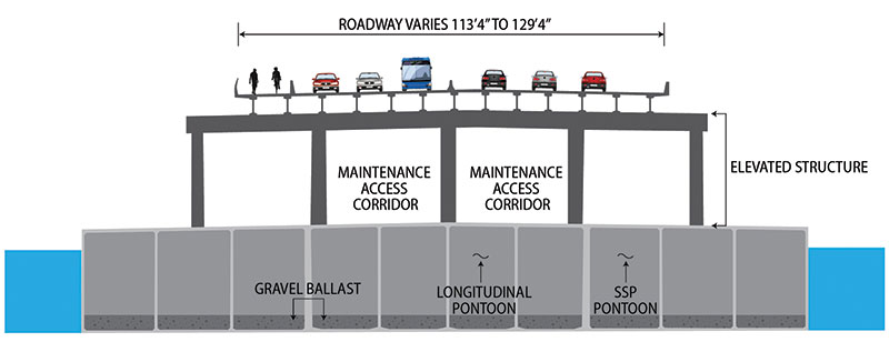
Cross-section of floating bridge.
The floating bridge is essentially a permanently moored floating structure that is laterally supported in the longitudinal direction and transverse directions by 3.125-inch diameter anchor cables. There are a total of 50 transverse anchor cables spaced approximately every 360 feet and eight longitudinal anchor cables which are connected near both ends of the bridge. Anchor cables extend as much as 800 feet and are affixed to specially constructed anchor structures at the bottom of the lake. The anchor cables have 60 tons of pre-tension to enhance their stiffness.
Ballast is a critical component of the floating bridge that allowed the contractor to keep the pontoons trim, or raise and lower the pontoons as required during various stages of construction. Water ballast, which can be readily pumped in and out of the pontoons, was used as temporary ballast during construction. When the pontoons are brought together for joining, adjacent pontoons are ballasted to within one half-inch of each other. A series of rams and winches are used to pull the pontoons together and align shear keys so that large, 20-foot long by 3.5-inch diameter post-tensioning rods, also known as bolts, can be installed. There are a total of 80 bolts evenly distributed around the perimeter at each longitudinal joint. Also, ballast must be continuously removed during the elevated structure construction to keep the pontoons trimmed within allowable tolerances while avoiding locked-in stresses in either the pontoons or the elevated structure. At the end of the floating bridge construction, all water ballast was removed and replaced with permanent gravel ballast. It should be noted that the bridge was designed so that a sufficient amount of ‘reserve’ permanent ballast is available for a future widening to accommodate light rail. The widened configuration would utilize the buoyancy from reserve ballast and require 26 additional SSPs to be added along the length of the bridge to offset the extra weight.
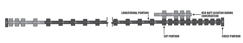
Plan view of pontoons.
Floating Bridge Design Philosophy
Unlike traditional land-based bridges in Washington State, which are usually controlled by seismic loads, floating bridges are governed by wind and wave forces. The floating bridge was designed to withstand a 100-year storm, defined as a storm having 98 mph winds and 6-foot waves. The pontoons, which are fully post-tensioned structures, are designed for zero tension stress in the pontoons under service conditions with rigorous crack control criteria for extreme loading combinations. At the extreme 100-year event, the pontoon hull reinforcing is designed to stay well within the elastic range. The elevated structure was designed to accommodate the imposed deflections from the pontoons and accelerations associated with the 100-year storm event.
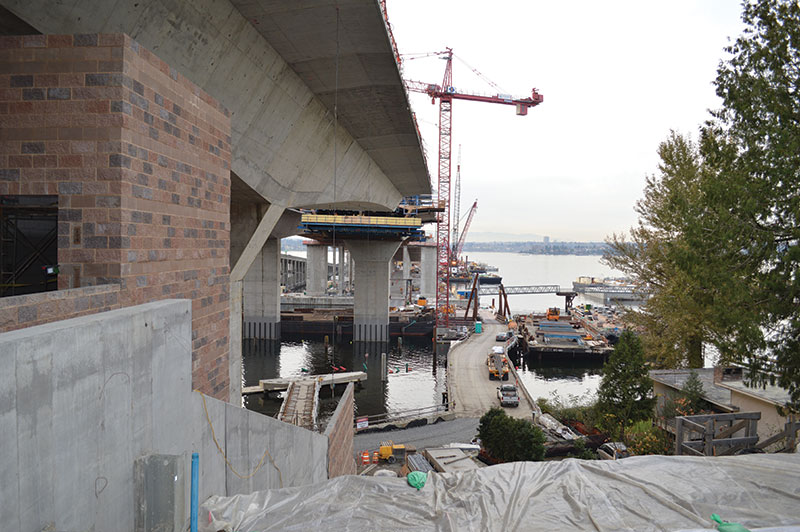
Aerial view of mainline bridge and BCD raft pontoon.
Construction Staging and Analysis
Assembly of the floating bridge required a highly planned, coordinated and choreographed effort to allow for multiple construction activities along the length of the bridge. For example, while Pontoons O and P were being joined, cross-beams and columns were being cast on Pontoons S and T and girders were also being set on Pontoons U and V. This orchestration of construction activities required careful coordination between the contractor, the project naval architect, and the project structural engineer.
The project freeboard criteria required that the difference in freeboard between opposing sides of the pontoons, and along the length of the pontoons over a distance of 360 feet, be less than 2 inches at all times during construction. Over 1,500 unique construction steps were analyzed as part of the construction staging process to ensure that freeboard and stress criteria were maintained throughout construction. At times, analyzed loadings exceeded contract freeboard requirements, and pontoons were pre-ballasted for 50 percent of the out-of-balance construction load to stay within project freeboard tolerances.
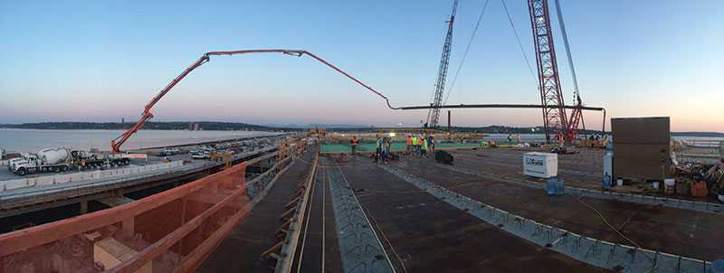
Placing concrete from the mainline to BCD raft. Courtesy of KGM.
An analytical model of the floating bridge using commercially available structural engineering software was developed to perform the construction staging analysis. For vertical and torsional loading, the floating bridge was analyzed as a continuous beam on an elastic foundation using roll, pitch and vertical support springs located along the bridge’s longitudinal axis to represent the foundation stiffness, in this case based on the density of water. As the bridge is constructed, the center of mass tends to grow in height as ballast is removed from inside the pontoons and the elevated structure constructed above. Since a pontoon’s roll stiffness is a function of both the water plane area and the mass center, the foundation springs were updated throughout the staged construction process. The construction staging model stress output was used to check floating bridge stresses for each of the 1500 construction steps analyzed.
The input for the construction staging analysis required detailed loading data from the contractor and naval architect. First, work activities for each construction step were developed and defined by the contractor. These steps were then analyzed by the naval architect who developed a ballast adjustment plan to balance the construction loads within contract freeboard requirements. For example, when a series of columns or crossbeam were poured, a corresponding activity to remove a proportionate amount of water ballast was required to keep the bridge trim. Once the construction activities and ballasting requirements were defined, the structural engineer used the structural model to check stresses in the pontoons and the elevated structure.
Pontoons B-D Elevated Structure Construction
Pontoon assembly and elevated structure construction progressed from both the east and west ends of the bridge. The last three pontoons, Pontoons B through D, were set in July 2015, which completed the assembly of the entire pontoon string. One of the biggest challenges the floating bridge project faced was finding a way to provide and maintain vehicular access for materials from land to the bridge. The contractor’s goal was to turn a ‘marine project into a land project’. For example, the ability to drive concrete trucks to a pour location versus having to tug a barge loaded with concrete trucks is a much more efficient and economical means of delivering concrete.
The east end of the floating bridge was more accessible than the west end due to its proximity to shore. A temporary bridge and several barges were linked to form an access trestle in the early stages to connect the easternmost pontoon, Pontoon W, to land. Once the east fixed approach structures and transition spans were connected, access shifted from the trestle to the finished roadway at the east end. At the west end of the bridge, Pontoon A, which is located farther away from shore than Pontoon W, was not readily accessible from land. To achieve ‘land access’ for the west portion of the bridge, a three pontoon string, consisting of Pontoons B, C, and D (known as the “BCD raft”), was constructed and then moored alongside Pontoons R, S, and T at the east end of the bridge. The superstructure was constructed on Pontoons B, C, and D while it was temporarily moored at this location. In addition to improved access, this allowed all construction activities to take place simultaneously.
Land to water access trestle.
A series of 8-foot-diameter Yokohama-type marine fenders, existing bollards, and mooring lines were used to secure the BCD raft to the main string. A small ramp between the two structures was constructed for access. Once the raft was moored, construction vehicles and crews were able to drive directly from land onto the raft. Concrete pours for the westerly high-rise elevated structure on BCD raft were done by staging pump and concrete trucks on the easterly high-rise portion located on Pontoons R, S and T. Columns and crossbeams were poured by driving pump trucks and concrete trucks from shoreline directly onto the BCD raft. Decks were poured with a 61-meter pump truck staged on the mainline superstructure. A 100-foot-long tremie pipe extension was connected to the end of the pump truck discharge and supported in the air by a 400-ton crane. Construction of the BCD raft elevated structure was completed in July of 2015. The entire raft was pushed as a single unit, like a large 1,000-foot-long ship, to the west end of the bridge where it was joined to Pontoon E and eventually the westernmost Pontoon A.
The grand opening of the new SR 520 Evergreen Point Floating Bridge was a historical event attended by over 50,000 people on April 2 and 3, 2016. The bridge officially opened to vehicle traffic on April 11, 2016. Currently, the old SR520 floating bridge has been decommissioned and is being removed from the lake. The old pontoons have been sold and will be repurposed and reused globally for port expansion, marine offloading facilities, marinas, an offshore floating stage, and breakwater construction projects.▪
Fun Fact
The bridge was officially recognized in April 2016 by the Guinness World Records as the world’s longest floating bridge.
Project Team
Owner and Pontoon Designer: Washington Department of Transportation
Prime Designer and Civil/Structural Engineers: KPFF Consulting Engineers, Seattle, WA, and BergerABAM, Federal Way, WA
Designer/Builder: KGM, a joint venture comprising Kiewit, Omaha, Nebraska; General Construction Company, Federal Way, WA, and Manson Construction Co., Seattle, WA
Naval Architect: Elliot Bay Design Group