
Log cabins have been around for a long time. The first evidence of these structures dates back to the Bronze Age in northern Europe.
They were used as temporary shelters because they were easy to assemble and disassemble. Fabrication and shaping of the logs were minimal and required very little work.
In 1600, immigrants from northern Europe introduced these log cabins to North America. At that time, they were very basic but quickly gained popularity because they incorporated many architectural features that made them suitable for living quarters. Horizontal logs, stacked one above the other, served as the exterior cladding with a good thermal insulation, and as the interior wall finish. In the old designs, gaps between the round logs were filled with clay reinforced with hay. However, round logs stacked one above the other to form a wall are inherently unstable. Only the interlocking of the logs at corners provided the stability. When cutting the logs for openings, such as doors and windows, only one corner would provide stability, which was insufficient. Vertical timbers, i.e. vertical girts, were then added to connect the loose ends of the cut logs and tie them to continuous logs above and below the opening, or to grade. The size of the buildings was dictated by the length of the walls, which could only be as long as the tree trunks used. Splicing of the round logs within the length of a wall was not possible without tie irons or very long spikes. Those were seldom used for round logs. In later designs, the logs were shaved flat at their mating surfaces to achieve a better seal and to make the walls more stable when fastening the logs together with spikes. It even allowed logs to be spliced within the length of the wall, which overcame the restrictions set by the tree trunk length. This flexibility enabled smaller log sections to be used. Interlocking logs at the corners were and are still used today as a hallmark of the cabins.
Log cabin structures are still popular today. They symbolize a return to environmentally friendly living. The log cabins that are manufactured today use router shaped logs for a tighter fit, as well as splines that are inserted into a groove in the top and bottom of the log. The spline seals the horizontal joint between the logs. Logs are fastened to each other by long spikes or log screws.
The shaping of sections for a tighter seal in some designs, however, creates some unintended consequences that jeopardize the life of the logs. These horizontal mating surfaces result in a tighter seal but do not drain rainwater that runs down the facade. Water can enter the joint and finds its way into the groove of the spline, causing dry rot of the log.
Treatment of Dry Rot of Log Cabin Walls
Dry rot in log cabin walls is generally treated by three methods. The choice of treatment depends on the extent of the damage:
1) If only a few logs are affected, they may be replaced by cutting out the logs and inserting new ones. This procedure, however, is not as straightforward as it seems. The logs are interconnected through matching contour surfaces or with splines in reglets that are destroyed during the replacement operation. It is impossible to reinsert the spines or match up the reglets unless the log is at a corner where the timber can be slid into place horizontally.
2) Another repair procedure is to treat the decayed logs with an epoxy or petrifying compound. The timbers are injected with a compound that stops the rot and solidifies the decayed wood sections. This procedure is very expensive and has drawbacks in terms of fire safety and insulation value. Though the code allows a one-hour fire rating for heavy timbers (most logs qualify for this provision), a code enforcement officer may not label the treated logs as one hour rated, depending on the quantity of resin that has been injected into the timber. Epoxy and petrifying compounds are more flammable than heavy timbers. In most cases, however, the one-hour rated construction is not required because the building may be a one family residence with not more than two stories, and may not abut a garage (which could require a fire rating).
3) The most radical treatment would be to shore up the roof and rebuild the walls. This alternative is not cost effective.
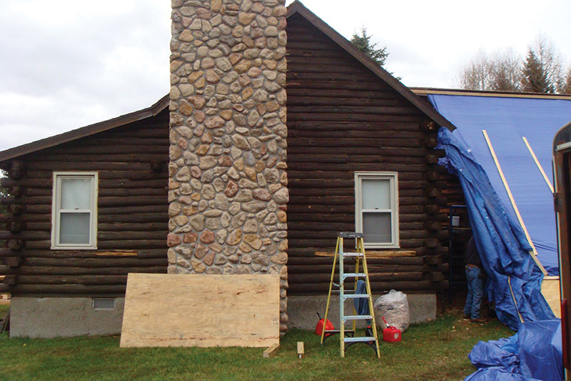
Figure 1. Elevation of deteriorated log wall.
The Log Cabin in Roxbury, New York
A log cabin in Roxbury had a dry rot problem. The logs on three walls had lost 50% of their section due to dry rot (Figure 1). The decay was on the exterior face of the wall, through half the width of the logs. The logs were seven inches wide and six inches high (Figure 2).
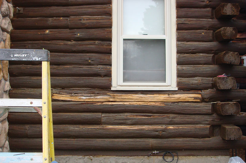
Figure 2. Close-up of rotten logs.
The log surface was highly irregular and had horizontal splits. An attempt had been made to seal the gaps with silicone sealant. The extent of the damage was such that the structural integrity of the building was in question. This structure, located in the Catskill Mountains, must support code loads based upon a ground snow load of 70 pounds per square foot (psf). As a result, the roof, as well as the log walls, must support the roof dead load and snow load, a total of 60 psf. The interior was not affected by the decay and exhibited the beautiful texture and wood finish that makes these structures so appealing (Figure 3).
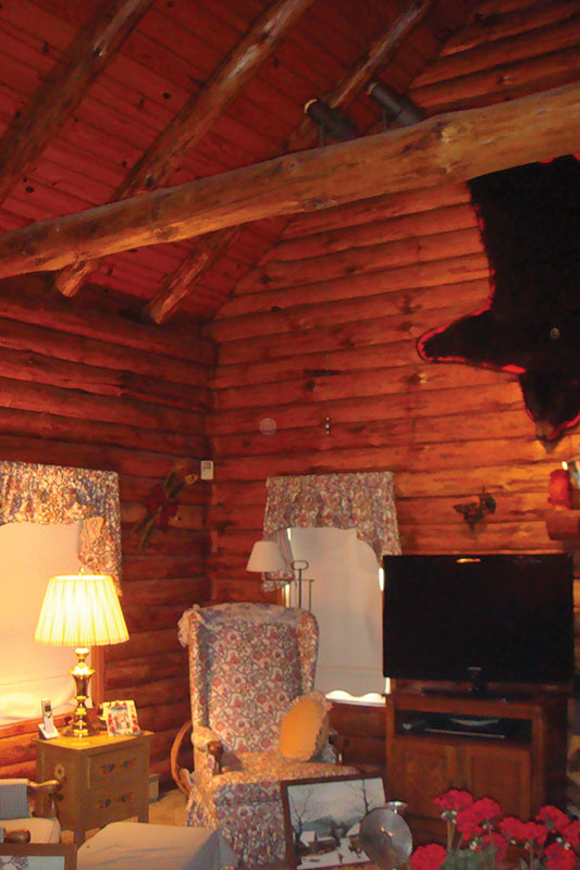
Figure 3. Log cabin interior worth saving.
The logs were shaved flat on the top and bottom with a groove in the center that received a continuous spline (Figure 4). This spline has no structural significance and is used solely to provide an air seal between the logs. Also, 10-inch vertical spikes placed alongside the groove at approximately 2 feet on center, tied the logs together. A close examination showed that the sill plate, on which the logs rested, and the top plate that supported the rafters, were in good condition.
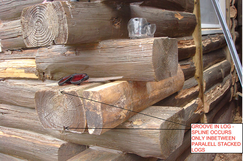
Figure 4. Log profile; note reveal for the spline.
The challenge was to find a solution that would retain the interior logs as finished walls but would at the same time render the walls structurally sound.
The Solution
The design was straightforward; however, the solution was a challenging one. Ultimately, this was only possible through the use of modern construction technology. Laser equipment and stud finders were the essential equipment in making this repair procedure feasible.
The solution consisted of removing the decayed wood and reinforcing the walls, which are 8 feet high, with pressure treated 4×4 posts and then covering the wall with a new exterior facing (Figure 5).
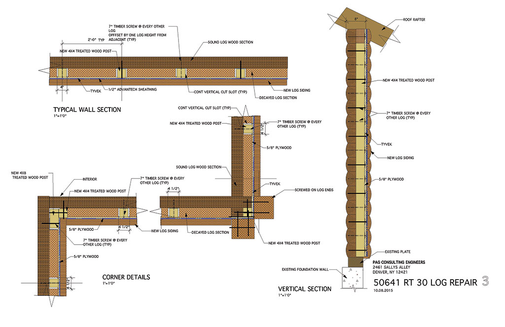
Figure 5. Contract drawing for repair.
The posts were designed to carry the roof load. They also served as stiffeners for the remainder of the log wall section, since approximately 50% of the 7-inch log width was rotted, leaving only 3½ inches of sound log material. The remaining 3½ inches stacked log sections formed a slender wall that required bracing. The posts then would be covered with a new exterior sheathing and log siding.
Since the work was done during the late fall and early winter, the area was enclosed and heated. A large tarp covered the area to protect the workplace and to enable the laser beams to be more visible (see below).
The procedure was as follows: vertical slots were cut into the outside of the log walls. The slots were 3.5 inches deep and 4 inches wide, extending from the bottom plate to the top plate. Slots and posts were spaced at approximately 2 feet on center, depending upon the location of windows. A stud finder was used to locate the spikes so they could be avoided when cutting the slots.
The design called for a ½-inch thick AdvanTech sheathing, an engineered moisture resistant high-performance product, on the outside to cover the studs. The studs needed to align to a common vertical and horizontal plane to fasten the sheathing. The log wall was very uneven, and there was no location on the structure that could provide a plane for such a reference. The contractor solved this issue by creating a virtual vertical plane parallel to the face of the existing wall using a laser as a guide. The tarp enclosure reduced the light in the work area so that the laser beam was easier to track. A constant horizontal distance from this virtual vertical plane was measured, establishing the cutting depth for the slots. Slots were cut with a small chainsaw and the wood (or what was left of it) chiseled out to a predetermined depth.
After cutting the slots, all loose and decayed material was removed. A preservative was then applied to the remaining exposed wood on the outside to discourage further decay. With the logs at 7 inches on center, the logs are 7 inches high; the posts were screwed to every other remaining log section vertically at fourteen inches on centers. At adjacent posts, the screws were offset vertically by seven inches so that every other post was screwed to the same log section (Figure 6). The posts, connected to the remaining log sections, provided the intended stability for the remaining log wall. The cavity left from the removed log material was filled with a closed cell insulating foam. The placement of the foam replaced and even enhanced the insulation lost by removing the rotten log sections.
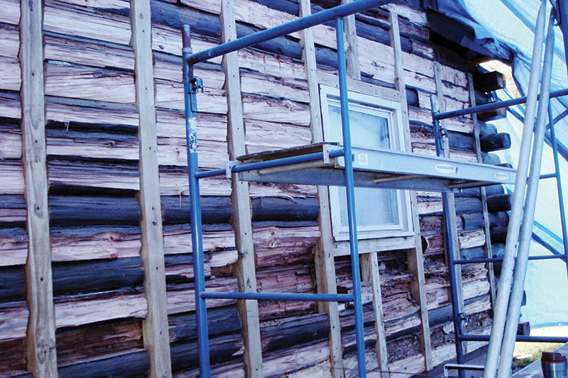
Figure 6. Staging of repair in progress.
The sheathing was screwed to the stud, and Tyvek protective barrier house wrap was stapled over the sheathing. New log siding was fastened to the wall as an exterior finish. The siding matched the old log appearance and was stained to match its color (Figure 7). The repaired wall ended up being 2½ inches wider than the original, and thus, new windows and doors had to be fitted with extension jams to match this new wall width.
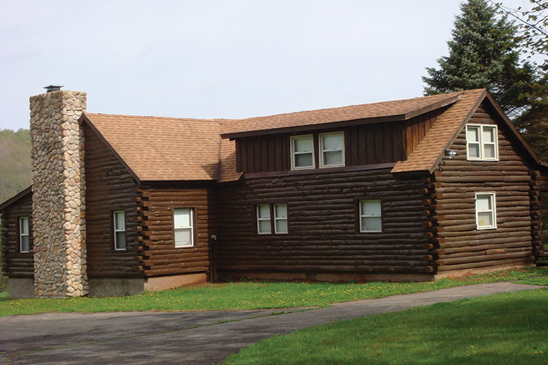
Figure 7. Log cabin after wall repair.
This repair procedure turned out to be very cost effective, considering the alternatives. It not only restored the walls but also retained the interior appearance of the aged logs. Also, it resulted in a house envelope that is now superior to the old log wall with its increased tightness, to control air infiltration, and its enhanced insulation properties.
What Can We Learn?
There are log cabins in existence that are centuries old and are still standing in good condition. The secret to their longevity lies not only in the species of the wood used but also in the detailing of the mating of the logs. When water is trapped between wood surfaces decay initiates. Thus, a good detail that assures drainage of the joint is the first step to the longevity of the structure. The details used in this log cabin were derived from the desire to achieve a tight joint that controlled air infiltration into the building. Thus, the builder used a spline and groove design. This design in itself would not have caused a problem, but in combination with a flat non-draining exterior top surface of the cut log, rain water running down the facade can find its way into the groove and get trapped. Moist wood, when not vented, causes dry rot.
Very rarely do dry rot problems occur on log walls where the outside mating surface of the log is slanted downward. Round logs, stacked one above the other, provide good drainage on the exterior curved surface, a feature of the centuries- old cabins that still stand today.
Another caution is in the use of sealants. No sealant is 100% waterproof over the long run. Sealants deteriorate over time and, when they fail, they can do more harm than good by trapping water. A sealant joint should always be configured so that it can drain once the sealant fails. Proper drainage is something to keep in mind when using sealants not only on log cabin walls but in general construction.▪